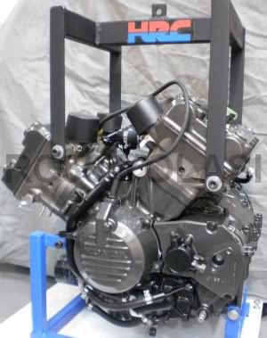
The RC30 Engine
A Sideways Glance
There are significant differences between an RC30 engine and the VFR that the RC30 engine was based on. I outline here the major differences that affect only the crankcases, something that only Honda would make big changes to. I don’t list all the details of the differences, it gets quite tedious and only those that already know would likely read it.
Differences between RC30 to Early (86-87) VFR crankcases:
- Quantity of main bolts
- Stator mounting
- Internal reinforcement
- Bearing size for transmission.
- Piston oil sprays
- Shape of cam drive chase
- Shifter mechanism
- Oil cooler ports and boss
- Filter boss
RC30 to Mid (88-89) VFR:
- Quantity of case main bolts
- Internal reinforcement
- Piston oil sprays
- Shape of cam drive chase
- Oil cooler ports and boss
- Filter boss
RC30 to Later (90-93) VFR
- Piston oil sprays
- Shape of cam drive chase
- Cam drive mounting
- Cylinder head bolting
- Oil cooler ports and boss
- Camshaft oil feeds
- Filter boss
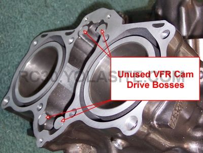
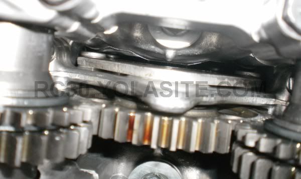
There are two different types of crankcases for the RC30. The differences are essentially cosmetic in nature. The later RC30 crankcases uses the same raw casting as the 1990-1993 VFR so the cast in gallery for camshaft oil feeds are present in the engine's valley. These gallery lumps are not bored through, but machined through on the RC30 crankcases. The VFR cam drive bosses are also cast into the cam drive chase. These bosses are partially machined away for the RC30 crankcases to make room for the RC30 cam drives that bolt to the cylinder head, not just the crankcases like the VFR-F. RC30 crankcases are obviously unique because of the machining done to them. If you have a set of replacement crankcases (11000-MR7-000) they will probably be of the later type. Honda did not change the crankcase part number for the later type crankcases because the machining to them was never changed. They are, for all intents and purposes, the same to Honda. One of the few complaints I have about the engine is the crankcases. They are very rough castings, have horrendous paint jobs, and have so much casting flash in them you wonder if the molds were set up correctly. It takes some work with a die grinder to remove the flashing. I've found big chunks of swarf in new-in-the-box crankcases. No wonder RC30 oil pumps are discontinued. Sucking chunks of aluminum through an oil pump can take it's toll (which is then caught by the filter).Hopefully any chunks head to the filtered crank/cam side of the oil system, not the unfiltered transmission side where it will plug those tiny orifices. There, I've said it. If everything is properly prepped there are no concerns. The No. 4 cylinder has been known to leak/weep coolant due to casting shrinkage also, but we won't talk about that.
The following two pictures are of the later style crankcases. A picture is worth a thousand words so here are two thousand words...
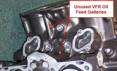
The unused / undrilled VFR oil feed galleries to the camshafts |
 |
.
The valves are nothing very special but they are expensive. They are hard faced so you have to be careful lapping them in. The tips are also heat treated so you cannot grind them, which normally wouldn’t be a problem unless something has gone really bad. As with any engine valves are best replaced rather than trying to refurbish them.
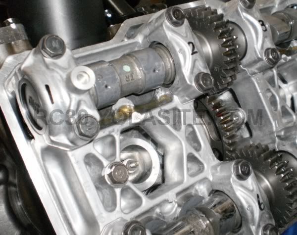
Honda was so enthused about the gear drive units for the camshafts they cast it into the cam covers. Gear driven cams are precise and very reliable. These are two characteristics are of significant value in a performance engine. The down sides are a possible weight and size penalty. More to the accounting point is that gear drives are significantly more costly to produce than chain driven cam systems. This is why the contemporary VFR engines no longer use gear drives. What a shame. Cam timing varies sooner, and to a higher magnitude, with chain drives versus gear drives. The Honda gear drives in an RC30 are nice units. To rebuild one completely is not as easy as it could have been though. Honda used four rivets to hold the gear drive side plates together. Rivets could be replaced, but sourcing the special clearance bearings is painful. The upper and lower bearings can be removed without removing the rivets but the center gear bearing requires rivet removal. Once you are in there it is unlikely you will be able to source the bearings though. They are not off the shelf.
The rest of the valve components are pretty standard designs. Valve locks, retainers and spring washers are not thrilling, even if it is an RC30.
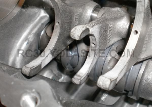
Rotating Assembly
The rotating assembly of an RC30 is pretty robust,
barring a few racing oriented components. The crank is pretty stout forged
alloy steel piece. If a crank fails it is something else usually causing the
trouble. The connecting rods, on the other hand, are somewhat delicate.
Titanium rods were selected for the RC30 due to the racing regulators insistence on utilizing standard components in an attempt to keep costs down. Honda said "bah" and just put racing connecting rods in to start with. I have a pile
of old Honda rods that are amusing to look at. Most of the rod failures
wouldn’t happen in a high performance steel rod. Personally, I think Honda can
keep their titanium rods, especially for a street engine. I’d rather keep the
RPM down slightly, if at all, and have robust steel rods I can forget about for
an engine’s lifetime. Steel rods and rotating assembly balancing for what you are using the bike for is a better option in my mind.
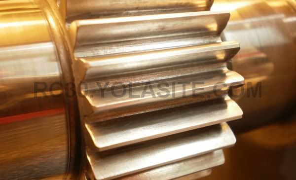
This is the drive gear for the camshaft drives located in the center of the crankshaft. This brand new crankshaft had quite a bit of scale on the gear teeth faces and roots. It was painstakingly removed during crank preparation. Other new cranks I have seen did not have this. Honda took a swipe at the scale with a wire wheel but the scale won. The scale was probably created during heat treatment as it was present on the face of the gear teeth. It wasn't a forging or tooth cutting problem. Most guys would have left it alone but I couldn't stand the thought of it flaking off.
The pistons are often referred to as two ring pistons. In reality the pistons have one compression ring and one oil control ring. In the automotive world these are maybe more accurately known as single ring pistons. Both the oil control and compression rings are pretty delicate and are the main reason an RC30 can use oil. Excessive ring blowby also creates more vapour going to the separator tank that can increase oil consumption, depending on how it is distilled and plumbed. RC30’s generally do not use oil if set up correctly. If an RC30 is using lots of oil then something is worn out. Valve seals are a common culprit for oil consumption in any engine, the RC30 is no different.
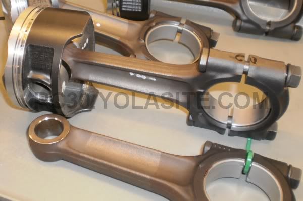
Some of the $500/piece titanium alloy connecting rods and the lightweight single ring anti-friction coated pistons. These rods are also anti-friction coated on the sides of the big ends. Nonferrous titanium rubbing on titanium is bad news as it galls easily and effectively welds the rods together. Not good in any engine. Aftermarket steel rods do not require this treatment but it can be done to them as a precaution or a micro power increase.
The primary drive is fairly standard except for the preload gear located on the primary drive gear on the right side of the crankshaft. This is done to eliminate lash in the same way as it is done for the camshaft drives. Eliminating lash altogether simplifies the installation of the primary drive over an engine that requires matching gear lash numbers. Production tolerances can be somewhat sloppier also. The starter clutch is located outboard of the crankshaft primary gear and (the inner part) is normally stationary while the engine is running, being fixed in place by the starter and the intermediate reduction gear. I will note that the double reduction gear for an RC30 is not the same as a VFR750. Outwardly very similar they do possess a different quantity of teeth.
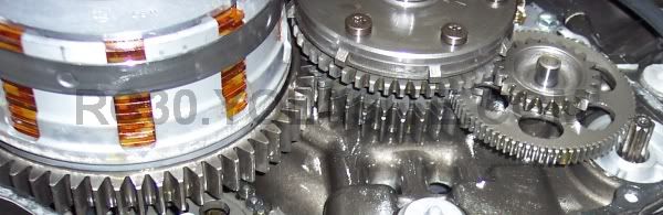
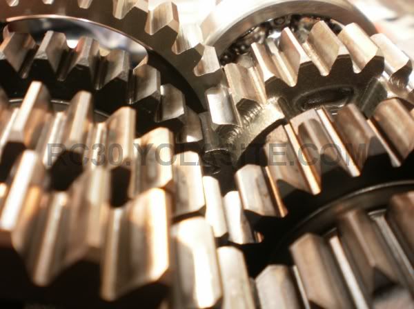
Gears, gears gears. The RC30 engine is full of them.
The slipper clutch is a design carryover from earlier Honda V4 engines. Even the early American style V4 cruisers used the design to make that Sunday cruise a little bit smoother. The slipper clutch design allows the clutch to slip only when the rear wheel is supplying torque, versus under power when torque is going to the rear wheel. The outer 7 plates in the clutch are permitted to freewheel when this occurs due to a sprag type bearing located in the center of these plates. The sprag unit effectively disconnects the clutch from the transmission input shaft. The inner plates are always (when the lever is out) fixing the clutch outer to the transmission input shaft. If the torque produced by the rear wheel exceeds the capacity of these inner plates the clutch will slip. This eliminates the rear wheel from locking up and the resultant problems created by lockup. The problems with such a system include a lot of wear parts within the clutch as well as the inability to use the clutch as a braking mechanism. The weight, or more correctly, polar inertia, is also increased as a result of the extra weight. You cannot get the back wheel sliding without the use of the rear brake even if you wanted to. I know that some of the earlier VF750 based race bikes eliminated the sprag style slipper but whether this was for rider preference or reliability I am not clear.

The sprag type slipper clutch for the RC30. The sprag unit is the bearing looking device midway in the assembly. You can see how the hub is two pieces with the inner (lower in picture) plates / disks remaining in operation at all times. The outer (upper in the picture) plates/disks function only when the engine is providing the drive. Pretty cool stuff but nothing new for Honda. The cruiser V Magnas had a similar unit in the early 80s and the VF bikes had them in the mid 80s.
The clutch outer has a strip steel ring on the outside of the basket to restrict the basket from flexing outwards under high RPM operation. A little bit of extra RPM creates a massive load on the basket fingers (a=v2/r). Without using a thick basket this was the solution for a space that is already cramped. A steel rod that passes through the center of the transmission input shaft hydraulically actuates the clutch. This rod transfers the force necessary to lift the appropriately named lifter plate and compress the two stacked diaphragm style clutch springs. Due to the slipper clutch mechanism it was necessary to use diaphragm style springs, as access through to the rear of the basket is not possible.
The transmission, as would be expected, is a six speed constant mesh type with the input (primary) shaft located forward of the output (countershaft). The transmission is like most Honda transmissions, clunky but strong. They don’t shift like a Suzuki but Honda never intended them to. The gears are all straight cut and have strong dogs. The gears themselves are spaced very close together ratio-wise for racing. The left side of the input shaft rides on a needle roller bearing and the clutch side is supported by a standard deep groove ball bearing. A needle roller on the right side supports the output shaft and a massive double thrust roller is on the left side. All bearings are replaceable except for the big honking one on the left side of the output shaft. If you need a new bearing there you need to replace the entire output shaft. The output shaft from a 1988 to 1989 VFR750F works, and is now the superseding part number. They are not identical, however. The sprocket on a VFR750 is about 1mm thicker towards the engine. If you use one of these VFR countershafts I recommend a 1mm spacer between the shoulder of the countershaft and the RC30 sprocket. It is also important when changing the countershaft to make sure you use the correct shims on each side of the countershaft first gear. Honda does not provide a side clearance, only a mechanic-proof color code, that I personally dislike. I know what the side clearance is but if you don’t know the color code you are, as they say, buggered. Honda puts the color code on the sprocket splines so when stripping an engine try to take note of the color before it hits the parts washer.
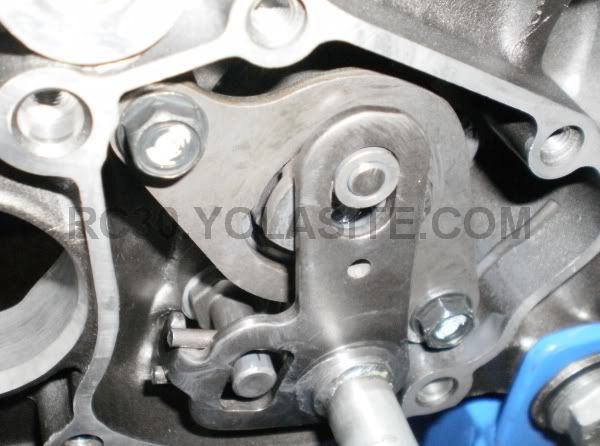
The gearshift mechanism for the RC30 is unremarkable
(sounds like an autopsy). All components are identical to the VFR750 barring
two components. The shift drum itself and the cast aluminum cover plate. The
cover plate differs not only in paint color but also in the use of a needle
roller bearing for the shifter crank to ride on for the RC30. Note that all
covers have the RC30 code MR7 cast into them, whether they are MR7 (aka RC30) parts
or not. This bearing is not listed as a part number in the parts books but if
you need one it is available through other sources than Honda. I have never tried a VFR shift cover
though it is likely interchangeable. You probably just lose the needle bearing.
The shift arm for a VFR750 rides directly on the cover casting. Another
possibility is to bore the VFR shift cover out for the HK1312 bearing.
The ignition system is a capacitive discharge (CDI) type with a pre-programmed ignition curve. It is not particularly extravagant by today’s standards but is reliable and provides good spark as modern CDI systems should. It doesn’t have a lot of fancy feedback loops to go berserk in the night, just sensors to tell the ignition where the rotating assembly is to pick the spot on the advance curve and to trigger the limiter. The ignition spark advance curve is pre-set and non-adjustable. Even the HRC units are pre-set. If you desire some adjustability in your advance curve and an increase in maximum RPM you will need an aftermarket CDI black box. I believe there is a guy in the UK who produces an adjustable curve CDI box but I have never tried it. If you don’t need it I’d stick with the standard parts. The ignition system uses only two coils. As with many engines more than one cylinder fires at once, the cylinder that is not in the correct position just doesn’t respond to the spark. There are restricted CDI units with different advance curves. Be wary when buying a used one. The spark plugs are 10mm items. I use NGK iridium tip plugs in the standard heat range and have never had a plug problem but I am not that fast and getting slower by the year. If you are running a heavily modified engine a plug read might show that a cooler plug is needed.
If you want to alter the static ignition timing (and dynamic) one way to do it with the standard CDI box is to modify the crank triggers so they are moveable relative to the starter clutch that carries the triggering knobbies. This is much less desirable than having an adjustable curve though, and again, for most purposes the standard non-adjustable CDI is fine.
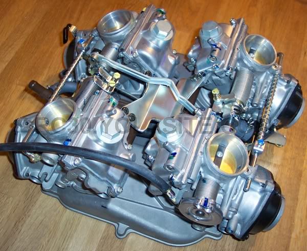
The four 35mm (sometimes called 38mm) bore Keihin CV type downdraft carburetors. These are brand new carburetors and a plenum for the 49 state US bikes. These are much more desirable than the restricted California carburetors. Note the extra lug on the plenum at the bottom of the picture which shows up only on the US carburetors.
The exhaust system on the RC30 is quite heavy and restrictive being a baffled type. Almost all RC30’s, contrary to what some say, use the same header pipes from the cylinder heads to the collector/muffler. I say almost because the later Swiss specification bikes have a plugged port in them, presumably for emissions testing. The Australian and early Swiss bikes also have different header pipes but I am still unclear what the differences are to the “normal” header pipes. The rear cylinder header pipes have a more tortuous route to take and poor cross section shape (ie: mashed) compared to the front cylinder tubework. The easiest way to unleash the RC30 at high RPM is to install an exhaust system with smooth bends and a straight through, non-baffled, muffler. In addition to the power increase you can save 5 to 10 lbs of metal. When installing a non-restrictive exhaust remember that some low end power can be lost as the aftermarket systems may use larger header pipes that weaken low RPM scavenging. The RC30 tends to be jetted quite rich as it comes from the factory and many people find that smaller main jets will deliver more power. There is a price to pay for running lean jetting and that is heat. Be wary of a dynamometer operator who installs smaller jets because the curve looks better, you may have difficulty with heat when riding hard, then immediately running slow. Small jets can make the bike snatchy and hard to ride also. With extremely lean jetting piston scuffing is a possibility. If you change the exhaust you will free up some power even if you don’t re-jet, though jetting is always recommended. There is a plethora of stock RC30 muffler part numbers. The exact differences between them are difficult to determine but there are some that are obvious. US spec mufflers have a paragraph stamped on them about the morality of the system, and Japanese ones have a tiny exit hole. Avoid the Jap exhaust unless you want to dissect it and convert it to non-baffled. That is what plasma cutters and Tig welders are for, right?
The intake system is basic. A two-piece plastic
airbox located under the fuel tank receives air from behind the steering head
above the top radiator. The non-reusable air filter is located inside the
airbox just to point out the obvious. Two different rubber inlet snorkels were
used; one is a large trapezoid shape, and the smaller inlet a more rectangular
shape. The USA and Japanese bikes use the smaller snorkel. This difference in
inlet snorkels dictates two different air filters, again one has a large
trapezoid shape inlet and the other is more rectangular. The flux area is about
20% different. Though there are various airbox part numbers the differences
amount to port size for the two different inlet snorkels and the USA bike has
additional port to feed filtered are to the air injection pump. Simply cutting
the hole to the trapezoid shape can derestrict the Japanese small port airbox
lower. The same story holds for the USA airbox but if you don’t use the air
injection pump be sure to plug that extra port or you will allow unfiltered air
into the engine. While on the subject of air filters there is a small plastic
box mounted to cylinder number three carburetor. Inside is little foam filter
that makes sure no dirt or dust gets into the diaphragm area of the
carburetors. Make sure this filter is in place and in good condition. I replace
it with the main air filter. The other, unfiltered, vent from the carburetors
merely vents the float bowls so does not require filtered air. There are, or
have been, aftermarket air filters made for the RC30 such as those by K&N
and ITG but I see little reason to use them. The Honda filters last a long
time, fit properly and don’t require modifications to a valuable airbox. You
also don’t have to clean them. I detest filters I have to clean unless it is an
MX bike. Avoid the using aftermarket stock style paper air filters. I have
bought a couple of them and they are quite simply garbage. These aftermarket filters do not have the
filter area of a Honda filter and use inferior construction materials. I have had them
show up in pieces because they were so old and brittle at the glued on end caps.
The fuel supply is by gravity so there are no pumps to be concerned about. Something you should be concerned about is the filtering of the fuel. There are two different fuel filters. The main filter is mounted to the petcock and is, as is standard, located inside the fuel tank. When servicing this filter take your time getting the petcock out of the tank, the filter can easily get caught up and torn. It normally wouldn’t matter but Honda quit making them and at the time of writing nobody in the aftermarket makes one. The second fuel filter (there is one per carburetor) is attached to the inlet of the float valve. They simply snap on to the float valve. These little filters catch on the carburetor body as you screw the float valve in so be careful not to tear them. The only way to buy these filters is to buy an entire, and expensive, carburetor gasket set from Honda.
The fuel line from the petcock to the carburetors, and the fuel lines located under the plenum should be checked on any bike that is now over 20 years old. If fuel has been left in the bike for an extended time these turn rock hard and crack. Even the blast furnace temperatures in this area are not the problem; it is fuel that hardens the hoses. With the advent of ethanol laced fuel the problem is exacerbated. I keep everything dry of fuel if I can. If these hoses leak your RC30 can turn into your own personal nightmare. The vent hoses under the plenum are usually fine even after years of service as long as they haven't been rubbing on something.
Oiling System
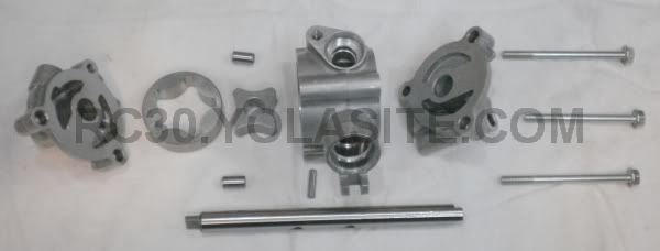
There are two discharge ports from the RC30 oil pump.
The smaller tube supplies unfiltered oil to the clutch and transmission. The
larger tube supplies oil to the filter that then passes through the oil cooler
(the HRC oil cooler/filter flow is opposite of this). After the cooler the oil
is directed to a main oil gallery that feeds the crankshaft main bearings and
rod bearings. The two center main bearings are restricted flow type in order to
provide adequate oil to the valvetrain feed galleries coming from directly above them. Externally accessible orifices restrict the two galleries to the valvetrain. These
orifices help keep the flow to the two crankshaft center mains
adequate but not excessive. The pressure of the oil to be filtered is kept at a maximum value
dictated by the relief valve located in the lower crankcase half.
Similar to the valve train feed galleries, the transmission feed gallery is restricted by an orifice located at the crankcase split line. The oil is then fed through a multitude of pathways and other fixed orifices to supply oil to the transmission components. Oil is fed to the shifter forks, main shaft/gears/bearings/bushings, countershaft/gears/bearings/bushings, and spray nozzles over the gears and the clutch via the mainshaft.
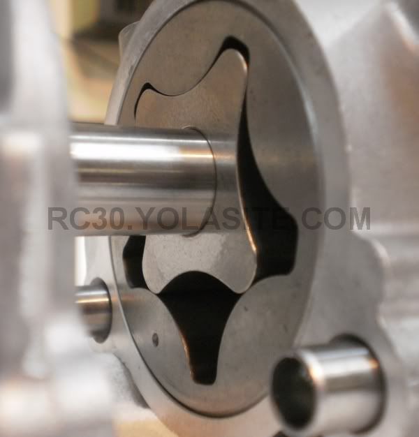
A closeup of an RC30 oil pump. Note that the mark on the outer rotor ALWAYS faces out.
A lot of people will advise running the oil level above the full line on the dipstick to alleviate oil starvation and the nightmares it can cause. I personally do not do this. I run the oil at the full mark and check it every time I ride. If you decide to run the oil ¼” above the full mark your oil consumption will go up due to windage. If you do stupid things like wheelie your RC30 it is very likely you will starve the oil pump and take out rod and main bearings. Running an extra ¼” above full on the dipstick won’t save you from such antics. If you ride so hard where you must wheelie then look at putting in a deep sump oil pan. HRC made them, Durbahn made them and you can always modify an existing pan. Of course then you need an aftermarket exhaust to clear the oil pan but that’s life.