Tools


Everyone Likes Tools

Motorcycles are cool and so are the tools.
 This page is about some RC30 tools you need and some you can live without. Some of these tools are home made, some are basic hand tools, and some are specialty Honda tools. This is not everything needed to work on an RC30; but it will give you an idea what you are up against during an engine or chassis rebuild.

 Shock Spring Holder

This isn't a fashion show, it is a shop where tool-wise form sometimes form follows function.  I needed to powder coat a shock spring so I invented this. After trying to figure out how Showa paints a spring I gave up and went down my own path. Maybe this is always how it is done, don't know.

This tool is made from an old ice chipper that didn't work very well, six concrete nails, some 3/8" threaded rod and various nuts/bolts. It worked absolutely perfect. I stuck the protruding rod through a crank checking stand so I could rotate the spring & tool as I coated it. See the News page (April 14, 2011)  for what it looks like after coating. I'll probably keep this tool in case I decide I don't like the color.

If you take a spring to an industrial powder coat company they will probably hang it from a wire and go to it. This leaves a tell tale mark where it was hung. Completely unacceptable to me. This tool leaves 3 small spots on the ends of the spring which you cannot see after installing the spring. I was also able to (more like had to) pre-tension the spring so after installation the powder coating would be under less stress than if coated a full extension. I pre loaded it to 500 lbs (approx 1/2" compression) for coating.

Shock Spring Holder

Piston Ring Setting Gage

The Honda shop manual says to use an inverted piston to push the piston ring down into the bore to check the ring end gap. I found it doesn't work using a Honda MR7 piston as they are shaped for the valve reliefs. Lots of engines are fine with that method of setting the ring in place, but it does not work here, the ring goes in wonky every time. To alleviate this I took a circle cutter and the drill press to some 3/8" thick Lexan. A pretty 8mm SS bolt and nylok nut finish it off. Consistently and confidently sets the ring at 3/8" below the deck. You could make this from many materials, but plastic is easy to work with and leaves no residue in your new engine. Transparent like this isn't necessary but gives it that Jetson look.

Piston Ring Setting Gage
Dial Indicator Extension

This is a tool most people don't need, or maybe even want. I had a situation where the cam timing was critical and needed to ensure they were dead on (and they were actually pretty good). I also find the Honda cam markings awkward to read. It could have been done differently. Combine this with the crude TDC marking with massive parallax makes you wonder if it really is together correctly. Even if you don't check the actual cam timing I recommend the use of a TDC gauge (see a different tool below) and a trusty degree wheel (also below) instead of the clutch cover/starter clutch markings. It makes the job enjoyable versus tensive in my opinion.

This tool allows me to sneak in and catch the top of the valve lifter. It is held by a standard dial indicator articulating stand. The dial indicator, on a separate stand,  reads off the end of the rod. I compensated for the weird angle to get an "equivalent" dial indicator reading to get to the 1mm lift. I couldn't measure on-axis. My gauge that would have worked was damaged so I compromised with this extension thing.

This is made from a needle roller from a digital overhead projector and a  rod drilled off axis to make the setup possible.

Dial Indicator Extension

Here is the extension in use.

Dial Indicator Extension

Cam Gear Pin

This has recently been replaced with the proper Honda part no. 94305-25162  (25142 for the shorter one). This pin is inserted to jam the preload gear so the camshafts can be removed or installed. This is not optional for installation. If you take a cam out (with or without the pin) you'll need one to put it back in. Pin is about 2.5 to 2.6 mm diameter. I use this pin with the Cam Gear Holder (below).

You could just leave the preload gears off the camshafts like some have done but then you'll need to:

  1. Mill the heads off so you can manually adjust the gear backlash using shims. Not much fun and you may be milling off a valuable head that doesn't need it.
  2. Have shims made up to get the backlash correct, you can't buy them anymore from HRC.
  3. Adjust the valves. The lash will go off after the backlash is corrected (it will decrease). You might get to do this twice if not perfect the first time. This doesn't matter if you are assembling a new engine, of course. You would have to do it anyway. 16 new shims, maybe a few less would be needed.
Cam Gear Pin

Cam Gear Holder

One of those tools I look around for, knowing it isn't really manufactured, but then happen to fluke it. This is actually for removing stubborn oil filters on cars. It just so happens on the smallest setting that it properly engages an RC30 camshaft preload gear. The handles touch together and it engages the teeth but doesn't grip them. I fixture the main cam drive gear in the polyethylene jaws in the vice and then use this tool to preload the gear and put the pin in. It is almost as if they designed it for the job. The spring doesn't feel very strong at all using this tool. The movement is very controllable. Do not over rotate the preload gear. It is a very highly stressed spring (looks like an internal C Clip) in it's normal state, let alone over expanded.

Update 120531 - I found a picture of it in action. See below.

Cam Gear Holder


Cam Gear Holder

Crankcase Alignment Pins

Two of these are screwed into the upper crankcase half at the front of the engine. One is screwed into the lower crankcase half at the rear of the engine. These "pins" reduce some of the mental stress of assembling crankcases. I use these with some spotlessly clean coated metal blocking on the clutch side. I get the crankcase halves started on the pins then they rest on the blocking as I fiddle with shifter forks. When I'm done getting the forks in place I pull the blocks out to lower crankcase half. You have to work quick, I like to do it in under a minute then let the cases sit for a few minutes without any bolt torque. I recommend a dry run if you have never done it before. After that, go fast. Have multiple torque wrenches preset and the torque pattern memorized. This is not the time to be looking for a socket adapter or wondering if that transmission orifice is the right way around.

These are 70mm long pan head screws with the heads cut off. These have since been plated and chromated. See the Project page for a picture of them in use in the upside down upper crankcase half.

Crankcase Alignment Pins

Long Hex Bits

These are sort of home made. They are long hex wrenches with the shorter leg cut off. You'll need to cut these with an abrasive wheel. These tighten the main cylinder head bolts (the 6mm hex) and the 3 little head bolts (the 5mm hex). I use a holder with these so the torque wrench can be used. Honda used to sell these but they are discontinued, as is the bit holder.

These bolts should have had 8mm and 6mm heads. Every engine has it's curse. Meet the curse.

Long Hex Bits

Balancing Devices

Almost had you there. Yes, these are just a couple front wheel bearings with the seals pried out of them. They are for static balancing of front wheels. I clean them out of all grease and apply 2 drops of oil before using them for balancing. I don't press them all the way in, I just get them parallel to the brake disk mounting surface.

Balancing Devices

Oil Filter Wrench

You get this tool "Free" with an oil filter from Honda. The part number is 15010-MCE-H51 for the tool and filter.

15010-MCE-H51

Lock Nut Tool

You will need this tool to Install the swingarm and engine lock nuts. Don't even think about doing it any other way. When using one of these crowfoot type tools don't forget to compensate for the added length if you use it with the handle axis in parallel with the torque wrench handle. If you don't you'll be over torquing. Part number for this black oxide artwork is 07HMA-MR70200. It is 1/2" drive and is hollowed out like it has to be for the 12mm hex. They went all out and laser  etched the part number.

07HMA-MR70200

 Another Lock Nut Tool

You will need this tool to tighten the nut holding the rear brake hanger to the rear hub. This is one of those times I got lazy. I could make something that would would work, it's not very complicated. Nonetheless this tool is very nicely manufactured. This one was made by Churchill for Honda. Honda subs out a lot of their service tool manufacturing.

Part No.    07HMA-MR70300

07HMA-MR70300

Clutch Nut Socket

This tool will allow you to get the nut off the clutch. Without this you will be in trouble. The large end is the clutch nut end of it. Use this tool in combination with the sprocket holder if the engine is out of the chassis (no rear brake to utilize). This is 1/2" drive and very nicely made.

This tool is part number 07716-0020203

07716-0020203

Riv Nut Tool

A tool good for replacing the often crusty riv nuts used on the RC30 frame and sub frame. The riv nut on the right is like the ones Honda used. The one on the left (my personal favorite) are good for fixing gimped threads where something was originally drilled and tapped. They set flush with the surface and are super strong. A good option where a helicoil isn't practical like the most forward mounting tabs for the RC30 seat cowl. These are 6mm but they are made in other sizes. Another high quality tool. This one is made by Sherex in the USA. Some companies make this tool more of a pop riveter but I like this one you crank with wrenches it's more precise. Worth the money.

Riv Nut Tool

Degree Wheel

I have no faith in those eye wrenching little marks on the clutch cover and starter clutch outer to find TDC. I like to use a TDC gauge (above) and a degree wheel for that job. I mount the wheel and wire tab on the alternator side  and read it through the valley of the engine. This makes valve adjustments and cam installation that little bit simpler.

You can buy these made of metal, but my experience says that one made of paper glued to cardboard is better (like the one below). I can plot it as big as I want, write on it, throw it out, or file it with the build log. Every engine is different.  I don't want to be stuck with an 8" anodized aluminum one that doesn't fit something, or could be twice the diameter. This one is about 11" in diameter for the RC30. Has a resolution of  about 0.25 to 0.5 degrees which is plenty good for dropping cams in. You'll never look at the starter clutch markings again.

Degree Wheel
Prelube Tool
When prelubing a rebuilt RC30 just spin the pump slowly to fill all the dry cavities. Many components are relying on the molybdenum disulphide grease so one goal is to not flush/wash that all out. If you are prelubing a laid up engine pump it around and around at full torque, and consider an oil change in there somewhere.

This tool was made from an old water pump that gave up the ghost. Every seal and bearing was gimped in it but it is good enough for this.

Note that if you don't have one of these you can prelube the engine by spinning the clutch basket counter-clockwise. To do this you will have to remove the primary drive gear.

When using a prelube tool like this the oil pump drive chain really needs to be disconnected.

Prelube Tool

 Upper Crankcase Stand

The Honda manual conveniently avoids the topic of how to fixture the upper crankcase half while you install the transmission, install the crank, install the rods and pistons (temporarily), check main & rod clearances, and mate the cases etc.. The crankcases for an RC30 are assembled upside down so I made this stand. It bolts to the two engine mounting lugs and one bolt through the cam drive securing bolt hole for a 3 point mount.  The first picture was taken as I was making it. The black crankcases are beat up VFR cases I use for such tasks. The second picture shows it fancied up in blue powder. I built another one after this one that is ever so slightly taller to ease the installation of a rod/piston on the rear cylinders.

RC30 Upper Crankcase Stand


RC30 Upper Crankcase Stand

Lower Crankcase Stand

This is the sibling to the upper crankcase stand. After the crankcases are mated you flip the crankcases over onto  this stand and finish the engine build. This stand makes the assembly a breeze.

Valve Organizer

This is my aptly named valve organizer. I use it when assembling a cylinder head. As I finish they get moved to the yellow side so they get put back in the correct hole. It is made from a cardboard box and plastic straws cut in half. They are the perfect size for a valve to drop in to. I put a blob of silicone on the end of the straw to hold them to the box. Not everything needs to be metal or last for a 1000 years. You can use wood but it is not my preference over this. I used to have a nice one made of wood but it floated away at the beach one day. I had a minor problem with my boat dropping a valve. At least it didn't have the valves in it.

Valve Organizer

Load Spreading Hoist Device

This is a device to help with lifting an RC30 engine. It connects to the four engine mounting points on the cylinder heads. A very secure way of moving an engine around the shop. Of course a cherry picker helps (not shown). This isn't all that useful for some but not everyone is the same.

It is made this tall so it will clear installed carburetors (not shown).

Load Spreading Hoist Device

RC30 Assembly Stand

This is a portable stand I made to hold an RC30 while it is being assembled. The steering stem and bearings need to be installed before the frame is supported by the stand. The engine could possibly go in after the frame is supported but it makes sense to loosely mount the engine in the frame too. Engine to frame bolting is torqued up later. If I didn't have hoisting capabilities the stand would look different than it does. A fair amount of both thought and blood went into this. The stand is strong and weighs about 75 lb sans wheels. The bike can be 99% assembled on this stand. Only the footpegs need to be bolted on after the bike hits the ground. In reality the bodywork is off during hoisting, but all the bodywork can be installed whilst on the stand for fit up.

The wheels have grease nipples/bearings and a ground OD. Normally the stand is supported on the custom made screws jacks. The wheels are only used when moving it, though they are way over designed and easily hold the bike up without flat spotting. The problem is that it rolls too easy, hence the jack-screws for torquing, etc. The front wheels are caster type (which is actually the rear of the stand when push it). The locks on the casters were useless for my purposes.

RC30 Assembly Stand


RC30 Assembly Stand


RC30 Assembly Stand

Below you see how the stand supports at the rear of the headstock. It is a fairly strong area of the frame that I targeted. Conveniently there are two holes here to put a couple pins through (see below). A set bolt (M10 x 1.25 - 12.9) is used to lock the pipes relative to one another. This picture illustrates why the lower steering stem has to go in before you support the frame.

RC30 Assembly Stand

Temporary Fuel Tank

This tool allows me to connect a temporary fuel supply to my motorcycles so I can start them without the fuel tank on, or to start them when I don't have or want fuel in the tank. It is made from an 8" long piece of 3" Sch 40 pipe welded to a 4" x 4-1/2" x 1/2" plate. It can be hung from the ceiling (my preference), clamped in a vice, or attached to a tripod. The baseplate is drilled & tapped for whatever I dream up on a particular day.

This is very handy during carburetor synchronizing or just a mid-winter fire up. You can buy these commercially but they are plastic. I like this because it weighs 8 lbs. I can modify it when I have to easily. You step on it and it is guaranteed not to break, bend, crack, chip or peel. It is 0.216" wall thickness so I merely tapped it for 1/4" NPT.

Temporary Fuel Tank
 
Temporary Fuel Tank


Rear Wheel/Tire Balancing Stand

The RC30 uses a single sided rear wheel that does not contain bearings within the wheel itself. This wheel attachment design makes it a challenge to statically balance. You can buy RC30 rear wheel adapters and stands but I had some Rc30 parts so I made one instead.

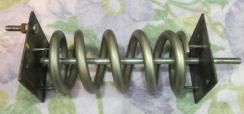
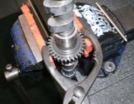
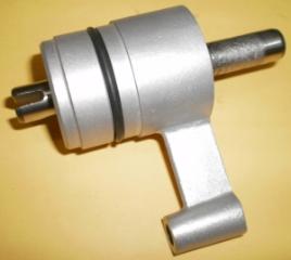
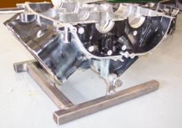
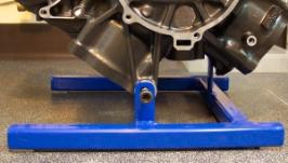
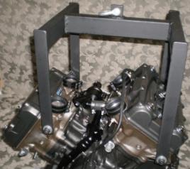
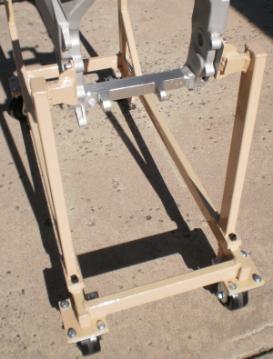
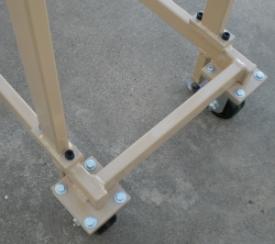
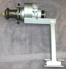
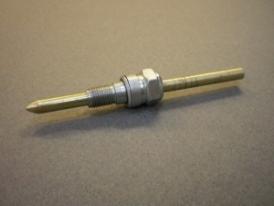
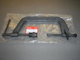
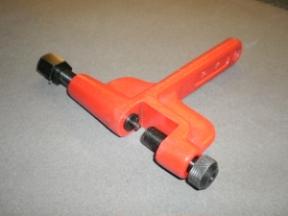
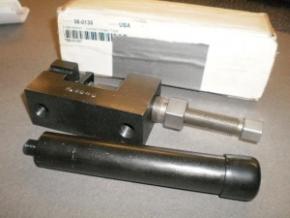
The stand is essentially the rear hub and axle mounted to a custom bracket that is gripped by a vice. There is slack in the vice end so it can be leveled as you tighten the vise. There are a couple of things that need to be done to make this work though. It wasn't just the custom bracket that was needed.

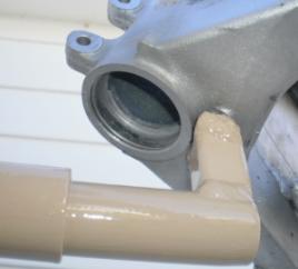
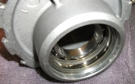
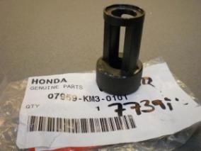
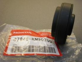
1. The Honda rights side bearing is a very wide needle roller with an inboard integral seal. Both of these are undesirable for balancing. I sourced a narrower needle roller bearing that does not have seals. This bearing will roll easier at near zero speed during balancing.

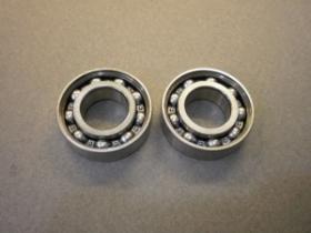
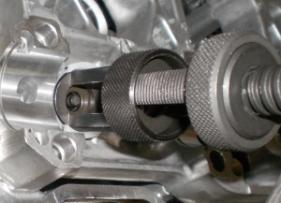
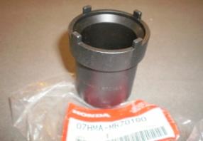
2. The Honda left bearing is a double ball roller bearing. I only wanted to use one bearing to reduce the friction at near zero balancing speed. I did this by removing the bearings and gutting the outboard bearing of the balls and inner race. I pressed both the complete bearing and the bare race into the left side. This ensured the inner (complete) bearing was seated nicely using the Honda tool. I would have preferred to gut the inner of the two bearings but that would make the bare race difficult to remove later.  As it is now assembled the bare outer race will just get pushed out by the inner bearing if you want to use the hub on a real motorcycle. Do not just leave the one bearing out. If you do, the aluminum casing will grip the remaining bearing too tightly so the axle will not rotate as freely as it has to.

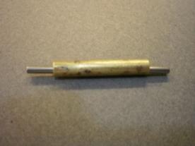
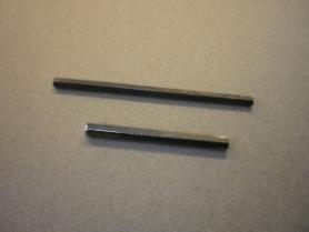
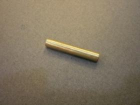
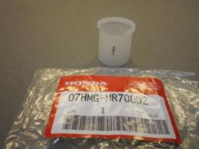
3. I didn't want to use a sprocket carrier or the spacers/washers so I cut off a piece of plastic ABS pipe to use in their place.

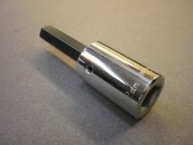
I was concerned that the axle would not be balanced good enough for use as a tool but testing showed axle balancing is not a concern.

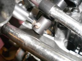
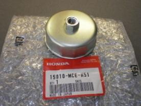
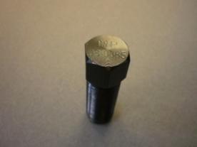
I think the narrow needle bearing was about $15. That was the only thing I had to buy to make this. The hub was a damaged one that someone had used a screwdriver and a hammer on to try to remove the "Nut".

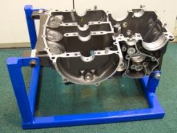
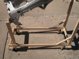
This balancer works better than I hoped for. It will balance to within a few grams and gives very consistent results. You can't ask for much more. It's fairly compact. I like the fact that I can easily take the wheel off, just like on an RC30. If you make one of these balancing stands be sure to address the bearings as I did or you will be disappointed in the performance of it all.

Ready to clamp in the vise, level and attach a wheel: Note that even if the vice becomes slightly loose it will not fall out and mess up your Magnesium RC30 wheel as it falls to the floor. It has some plate on top and bottom to catch the vice jaws. I used a swingarm pivot nut for the wheel nut. It's not correct but the thread is the same, and has a smaller wrench size than the big chrome nut normally used. The sprocket carrier nut is standard Honda. You can see part of the black ABS pipe spacer that it tightens against.

Rear Wheel/Tire Balancing Stand

The left side bearing(s). Note the outer bearing of the two is missing it's inner race and balls/cage. This simultaneously reduces bearing friction by half, and ensures the other bearing isn't squeezed too tightly by the housing.

The right side bearing I pressed in as far as the Honda tool would allow me. The Honda bearing is wider so they get fully seated with the Honda tool. This bearing goes in easy, so it goes in really straight. This being the floating side of the axle it makes no difference if the needle bearing is seated against the housing not, as long as it is straight. If I did this again I would press in a bare left side (ball bearing) race in with it to help expand the housing.

Valve Setting Punch

Hardly worth putting in here. Honda recommends tapping on the valve stems after installing. I use this little piece of 1/4" brass rod against the valve stem. I think I necked it down to about 4mm.

Valve Setting Punch

12mm Hex Socket 

This is a tool needed to remove/install the swingarm pivot bolt. A nice tool made by Armstrong. It is shown with the shorter original 12mm hex bit. I ultimately had to chop up a long 12mm hex wrench to make a longer bit for it. This tool has replaceable bits so I just swap the bits out when I have to. This tool has to reach through the lock nut tool 07HMA-MR70200.

07HMA-MR70200

TDC Gauge Extension

RC30 pistons are a long way down from the cam covers. I needed to get down in there so I made this tool.  A dial indicator reads off the end of the rod. I never realized how hard it would be to gut a spark plug. Try it sometime.

I drilled the plug out a thou larger than the rod. This tool cannot bottom out and more importantly the rod will not fall into the cylinder even if the piston is down. Think about it.

TDC Gauge Extension

Flywheel Tool

Nothing too fancy here. You need this to get the flywheel off your RC30. If you are a hack you can use an impact wrench on it to get the flywheel off but I recommend you use a flywheel holder. See flywheel holder below.

This is a Motion Pro number 08-0085. I think the "black oxide" coating is paint or something. It works fine for me but the tip would have been better if it wasn't cut down on the OD, it engages the crank just outside the flywheel bolt's hole.

Motion Pro number 08-0085

 Flywheel Holder

I like this home made tool. Without something resembling this you cannot torque the flywheel retention bolt on. Honda make something similar but it is very expensive and not as robust. Made from all kinds of flat bar, 1/16" thick rubber, angle, pins and square tubing. This was phosphated and powder coated.

In theory you could use the primary drive locking tool to lock the crank on the opposite end, but then bolt torque goes through the entire length of the crank which is not desirable.

I got the idea from an early Edison electric chair I saw at Greenfield Village.

Flywheel Holder

Below is the flywheel holder in use. This tool  can easily do the 61 ft*lbf for the flywheel bolt.

Flywheel Holder

Sprocket Holder 

This thing is ugly but it works. Made from some #50 agricultural chain, 3 layers of 3/16" plate welded together and a 1/2" stainless steel drive welded on that I cored out of something a long time ago.

With this you can not only attach the sprocket, you can  tighten the clutch nut when the engine is out of the bike Put the bike in 6th gear and tighten away. Of course you need the clutch nut tool to make it all happen.

Sprocket Holder

Valve Spring Compressor

This is the correct Honda tool, part number 07757-001000. The only thing of importance here is the retainer end which is not correct for an RC30. It has too large of a diameter so it won't fit in the lifter hole. You need a screw on attachment that will fit in the the valve spring retainers on an RC30 and slide into the lifter hole (Honda makes it, see below). This is a nice valve spring compressor for the price. It has a quick release and is compact and light weight. Not as clumsy as some.

07757-001000

Valve Spring Compressor Attachment

This screws onto the Honda Valve Spring Compressor (above) so you can use it on your RC30. This attachment perfectly fits the MR7 style valve spring retainers. It is very slightly too small for the KW3 style retainers that now supersede the MR7 ones, but it does work fine. A high quality tool, but a revision may be in order Honda.

Part No. 07959-KM3-0101

07959-KM3-0101

 Valve Lifter Hole Protector

You could make this tool by cutting up a 35mm film case (do they still make them?). The only problem I see with that is the possibility of shavings of the soft film case accidentally getting in the engine. I say that in order to justify my behavior.

I went in with both barrels-a-blazing and bought the correct Honda device. It is expensive for what you get, but it is well made, of what appears to be pretty tough Nylon or Teflon. It shows tooling marks and fits just like a Honda tool should. The part number, if you feel extravagant, is 07HMG-MR70002. I think the 0002 means they changed it twice since conception. Nothing like perfection.

07HMG-MR70002

Here you can see the 3 Honda special tools in action.

07HMG-MR70002
07959-KM30101
07757-001000

07HMG-MR70002 07959-KM30101 07757-001000

Steering Stem Bearing DIe

Honda uses a lot of expensive tools to remove and install steering stem bearings. I have some of them that I use with some of my own home made devices, and if it's a loose frame, a hydraulic press. This tool is used to press the bearings in. I don't have all the other parts here so this is all you get.... 07946-KM90200  I like how Honda puts o-rings on their tools so they don't transform into slide hammers and pinch you.

07946-KM90200

Steering Stem Socket

This tool will allow you to properly torque the steering stem nut. Your friend, who's really handy with cars and stuff might use something completely different. This is 1/2" drive and very well made like most all Honda tools.

This is part number 07HMA-MR70100

07HMA-MR70100

Chain Breaker

The best way to install a chain is to use an endless type supplied in the exact length. If you are not up to removing the exhaust, wheel, swingarm shock linkage, half your knuckle skin etcetera you will need one of these to push the pin out of the old chain. I have used this on 530 chain with no problem. It is made by RK but I don't know the part number. It also came with a ratcheting wrench, not shown. Casting looks Chinese but who knows these days.

RK Chain Breaker

Chain Riveter

This is required to set the pins in your new chain. Slap yourself hard if contemplating using a clip link in an RC30. This tool wasn't expensive and will rivet those links on so they never come loose. The next best thing to an endless chain. When done correctly it is essentially that. Always rivet to what the chain/link manufacturer requires. Always use a link made by the chain manufacturer, no mixing and matching.

This particular tool is made by Motion Pro and is pretty well made. It will do quad staking with the optional die or regular riveting. This also performs the functions of a chain breaker.

Motion Pro Chain Riveter

 Cylinder Head Stand

This took me a bit of time to put together but is a real pleasure to use. A bracket bolts to the cylinder head (with 1/16" rubber between) using the three small cylinder head bolts. The bracket then bolts to the stand. This allow either side of the cylinder head to face up. Face the combustion chamber up for guide removal, valve seat cutting or valve lapping. Flip it over for guide installation, or assembly of the seals, valves, springs, retainers and locks. This stand is designed so the head can be fully assembled with the head bolts etc.

Subsequently I made a 100mm long extension to better associate with the Honda valve spring compressor.

If you don't want to do this you can prop the cylinder head up on some old 2 x 4 boards as shown in the HRC racing manual.

RC30 Cylinder Head Stand


RC30 Cylinder Head Stand


RC30 Cylinder Head Stand

Rear Hub Service Tools

There are a number of bearing tools you need to service the rear hub and bearings. I have lots of generic dies and such, but again I bought the Honda tools specifically for the task. They work good but are pricey and can take eternity to get if they aren't in stock, and they won't be. Some of these tools like the handle and the small die are also used for installing front wheel bearings.

Resist any urges to use these with a hammer like a cowboy. The only way to work on the hub is with a nice hydraulic press. Front wheel bearings can be tapped in with this tool, but the big needle bearing and the doubled up ball roller assembly in the rear hub take some nice even force to put them in properly so they last.

From Top to Bottom
  1. 07746-0010300 - Bearing die
  2. 07746-0040900 - Guide
  3. 07746-0010400 - Bearing die
  4. 07746-0010500 - Bearing die
  5. 07749-0010000 - Handle
07746-0010300


07746-0040900


07746-0010400


07746-0010500


07749-0010000

Primary Drive Tool

This is a jamming device for the primary drive. It allows you to get the big bolt off the starter clutch/primary gear by placing it at the top side of the gear set, or installing the bolt by placing it on the under side.

This was made from a 1986 Honda VFR750F primary drive gear. I made 3 of them from one gear. I had to grind the notch in it to clear the ignition pickup mounting boss.

Honda makes a similar tool but when you a have useless primary gear on hand this made sense to me. Honda's is a bit smaller and more of a universal fit. Conceptually identical, except this one is better suited to this particular engine

I refuse to use the method of jamming a rag between the gears of any bike, let alone an RC30.

Primary Drive Tool

Here is one of them being used to take the bolt for the primary gear/starter clutch off. The starter clutch and bolt aren't shown.

Primary Drive Tool

Make a free website with Yola