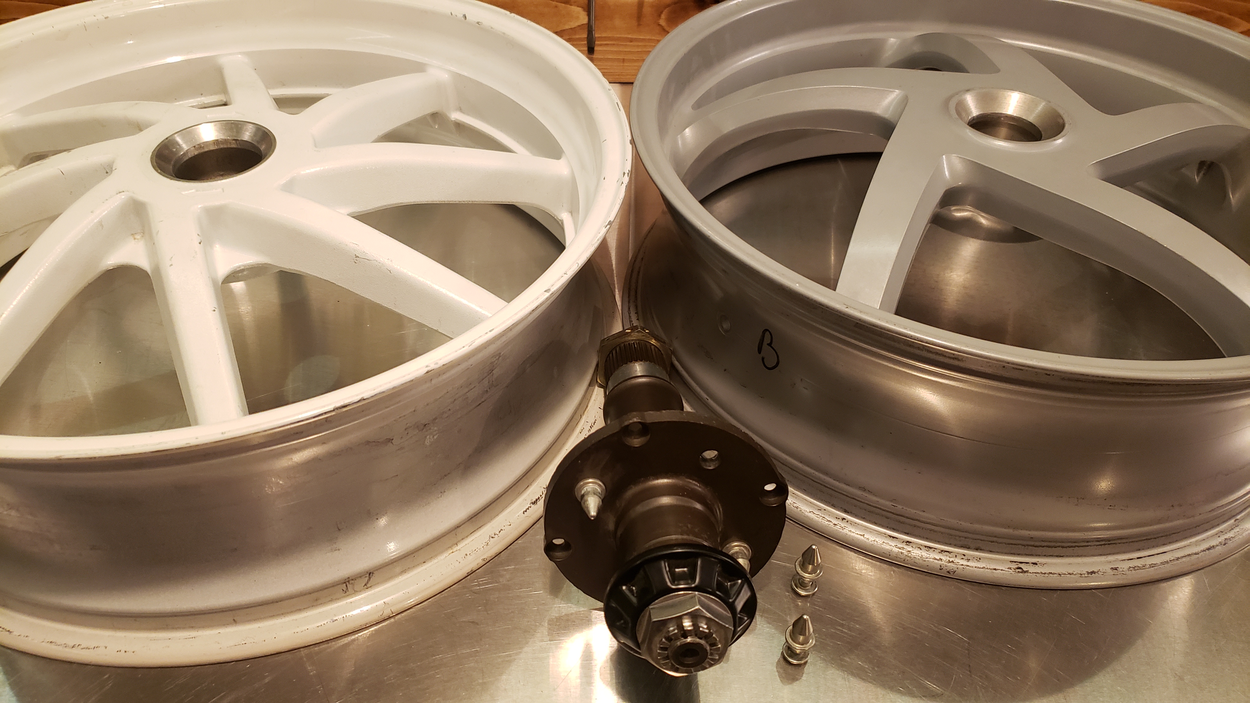
My wheel is a 17" x 5 1/2" wheel from a Ducati 1000cc Uglistrada. These wheels are nothing special, just cast aluminum, no fancy forging, or scary rotten magnesium alloys. The wheel is made by Brembo/Marchesini. I never bothered crack checking it because it had zero damage and the original paint. It also spun with essentially zero runout on my custom rear wheel balancing stand (see the tools section). I didn't want to DyePen test it because the dye will mess up my white powdercoat job.
A straight stem will NOT clear the pro-squat linkage. Don't even try.

This wheel takes an 8.3mm diameter tire valve stem, not what I am accustomed to on Japanese machines. If you need a valve stem you should get a genuine Bridgeport forged item. The following Bridgeport part numbers are for the 83 degree stem version that comes standard with Ducati wheels and are good for ~ 210 km/hr. That is a lot faster than the wigglies want me to go.
40 450 1501 - Bare40 450 1535 - Silver40 450 1539 - Red40 450 1533 - Black40 450 1534 - Gold40 450 1527 - Blue
An example of the donor bike for my wheel. That is one ugly machine ! I debated putting an image of such an ugly bike on my website. Only a mother can love that thing.
Problem 1 - The wheel bore for the axle is smaller than the Honda wheel and needs to be bored out. Don't even think about modifying the axle.
Problem 2 - The wheel offset is incorrect. My measurements, taken using reasonably precise instruments, result in a spacer being needed behind the Ducati wheel. Even with a spacer the wheel comes quite close to the swingarm as the curve of the swingarm and the smaller 17" wheel radius conspire to make for an even tighter fit.
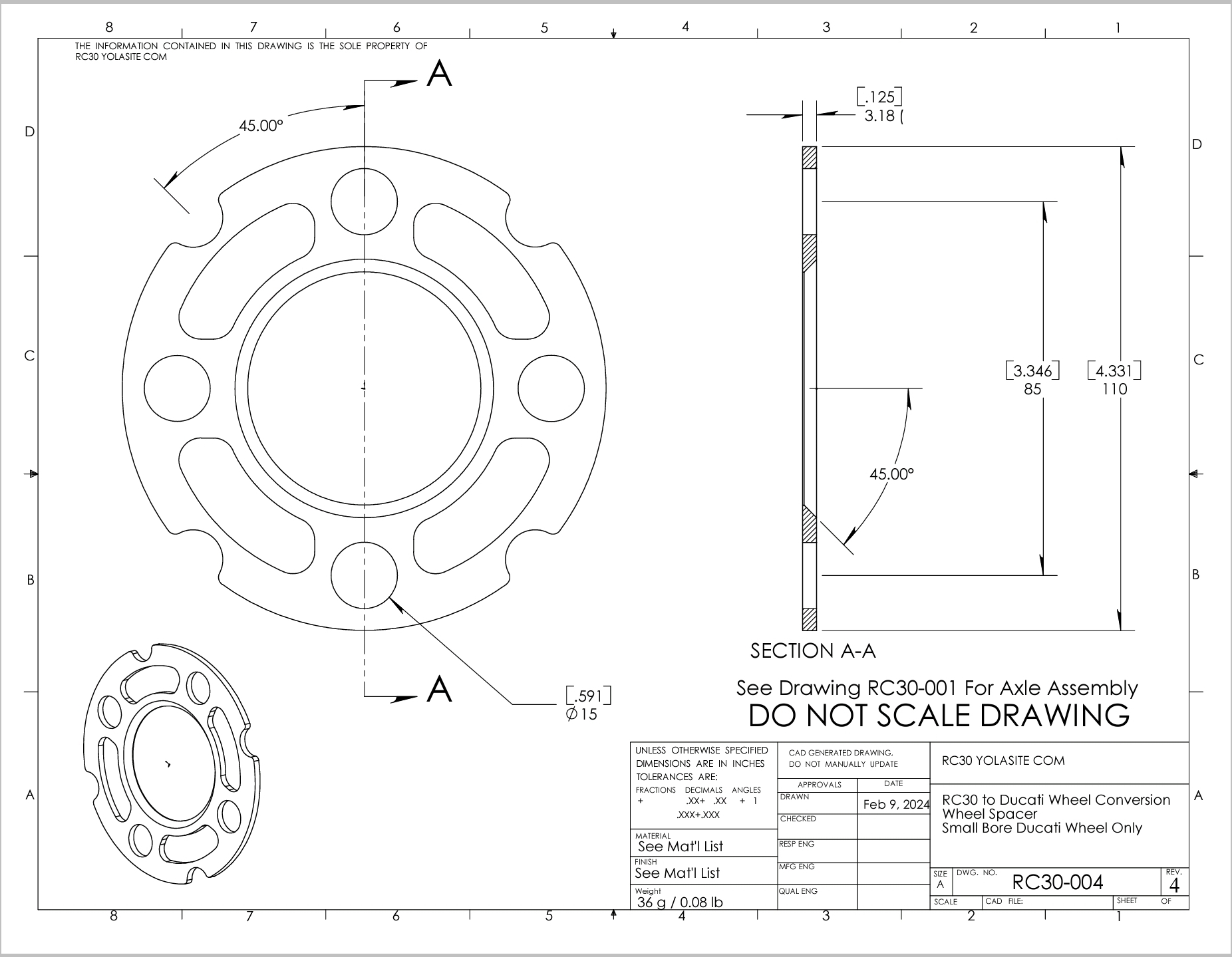
The spacer dimension I calculated was 2.95mm. I used 1/8" or 3.18mm. I don't think 0.009" is going to make any difference. If you think it will you have OCD worse than me.
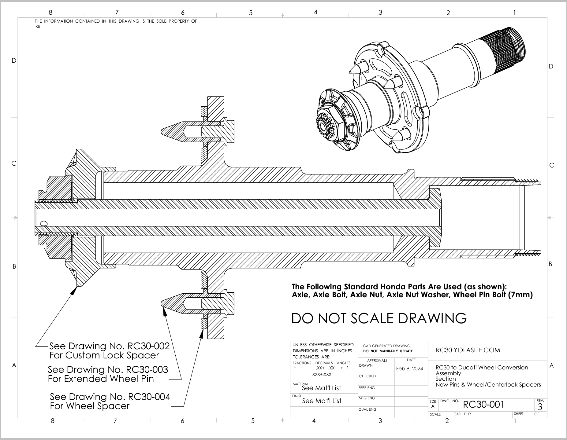
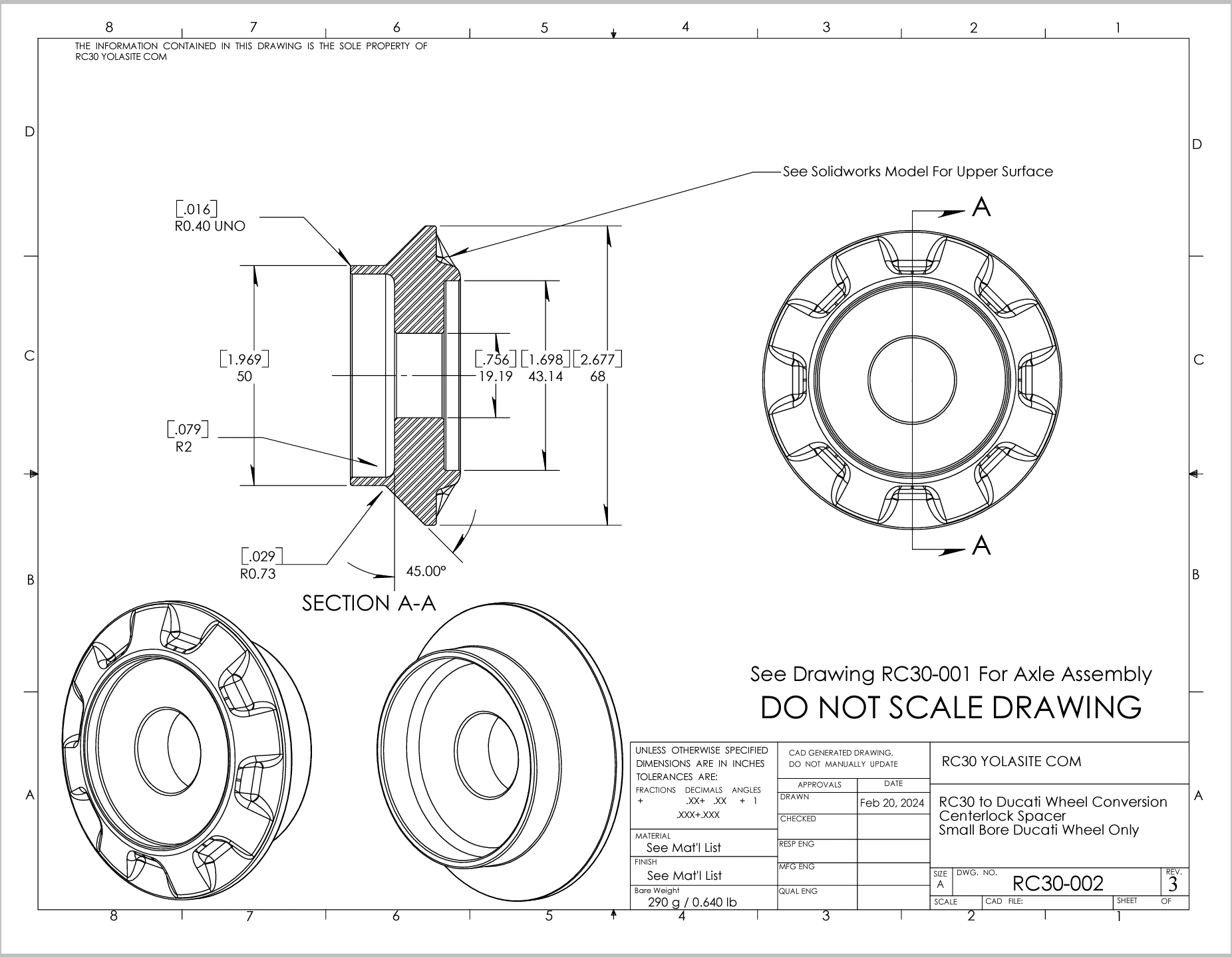
Problem 3 - The thickness of the Ducati hub is more than the Honda. This is an issue compounded by the fact that the necessary spacer (see Problem 2) adds to the thickness. The original centerlock spacer will no longer engage on the end of the axle. I designed a custom centerlock spacer that will both engage the axle, and allow room for a cotter pin using the standard Honda castellated nut and the stainless shim/washer.
Problem 4 - The tire valve stem (yes, even the original Ducati angled stem) hits the pro-squat linkage in standard configuration.
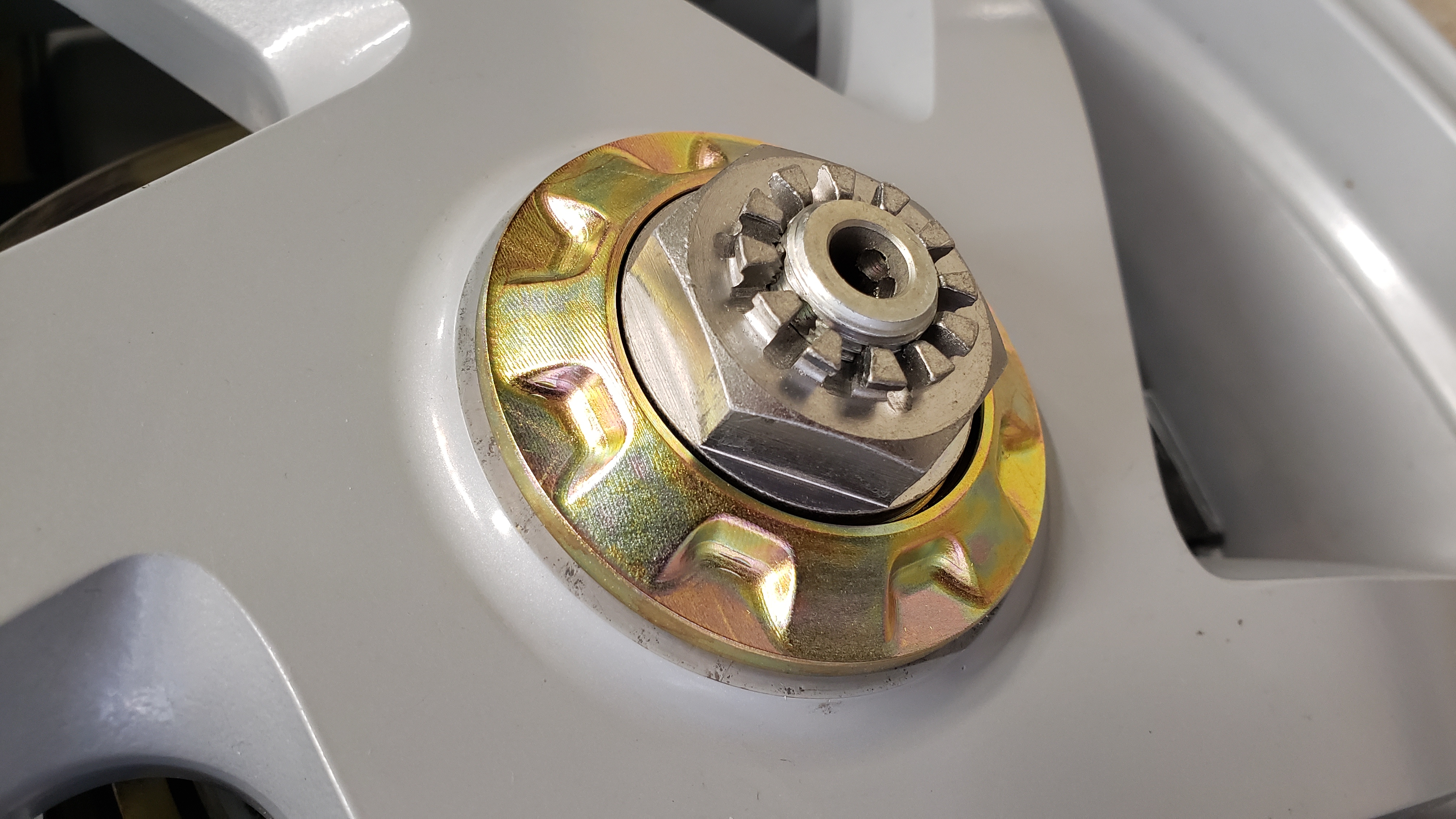
This does alter the geometry of the pro-squat linkage a bit. Doing a one spline relocation also rotates the brake caliper clockwise on the axle looking from the starboard side. This moves the brake line a small amount, but it was negligible. No special brake line is needed.
The clearance between the pro-squat linkage and the Ducati wheel spokes is also increased by re-indexing the arm. Clearance is about 4mm prior to doing the valve stem fix.
.jpg?timestamp=1711144305509)
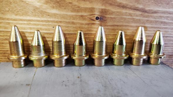
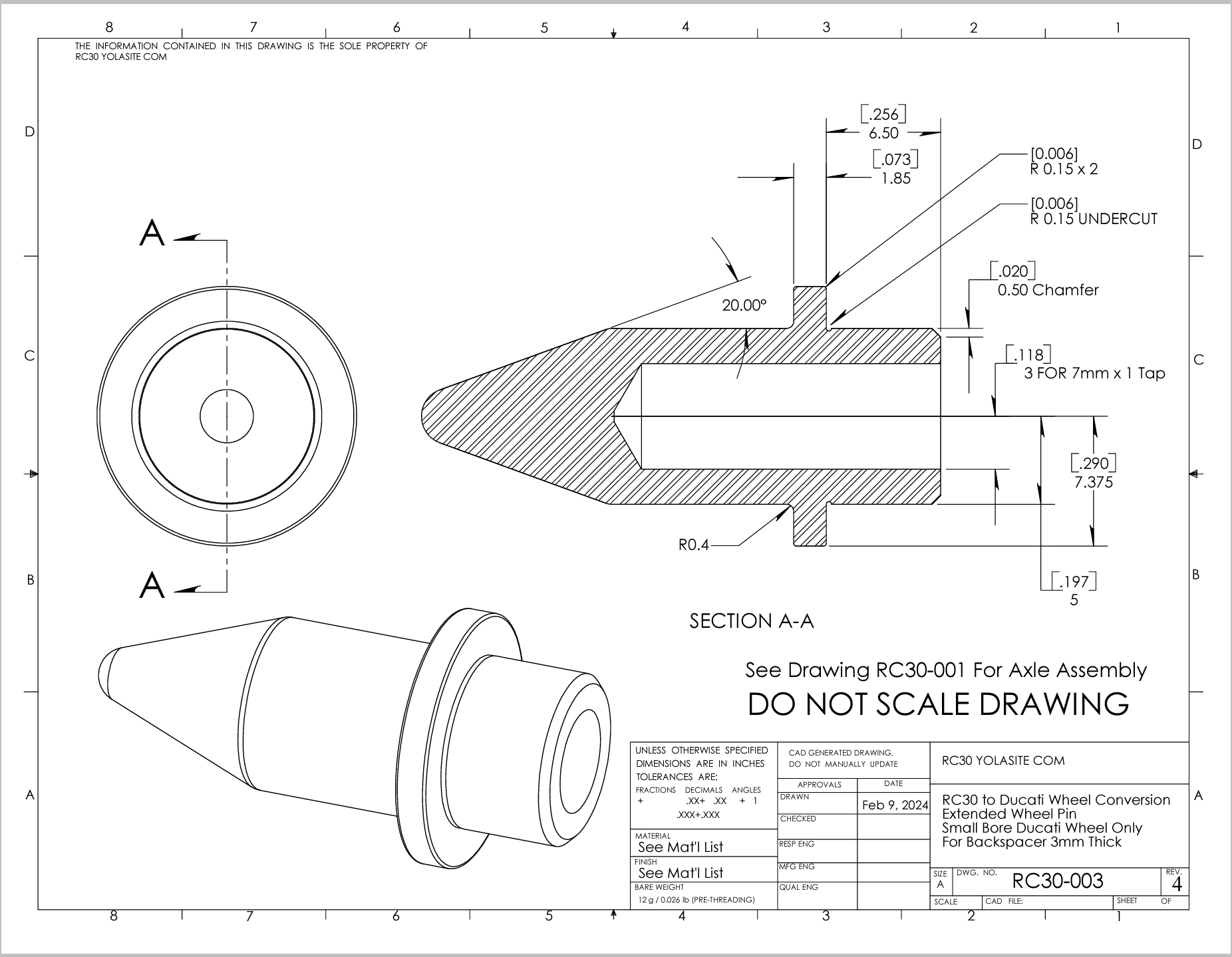
Problem 5 - Wait, you said four problems! Yes I did, but Problem 2 of adding a spacer results in the wheel pins being effectively shorter than Honda intended. I am sure some people would say this is overkill, but I do what I want, not what you think I should. Since I wanted to retain the option of easily mounting the 18" Honda wheel my spacer will go outside the shoulder of the pins. Doing this required me to have four pins made that were 1/8" longer (the spacer thickness) on the pointy side to give a similar engagement with the wheel.
You could put the stock pins on top of a spacer but the axle would need to be pulled out to remove the spacer to use a stock wheel. You would not have much of the pin pressed into the axle either. Pins with a longer pressed in portion would be essential. You decide but easy removal of the spacer means a lot to me.
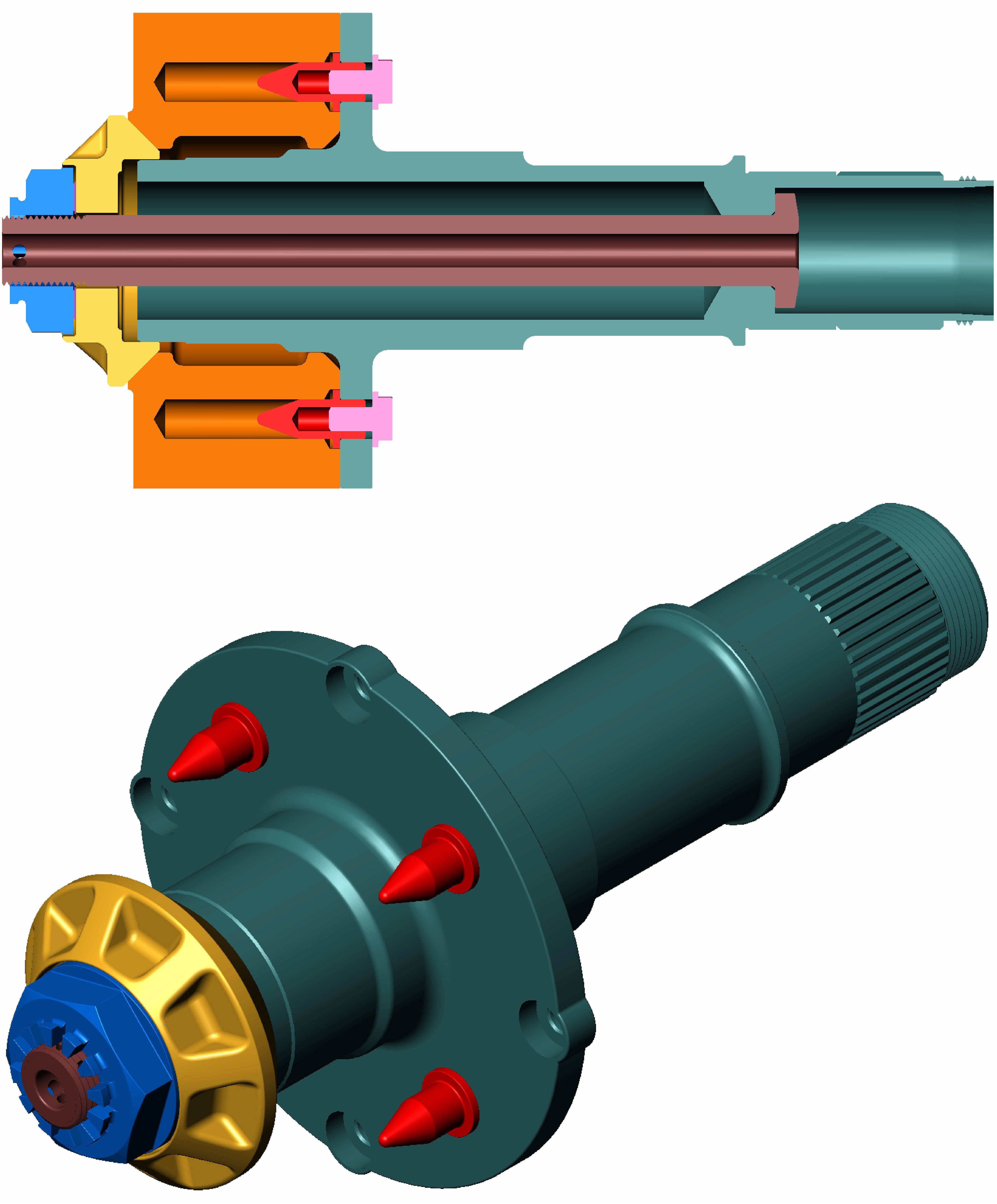
Below is a 3D Assembly Model of the ORIGINAL HONDA DESIGN for reference:
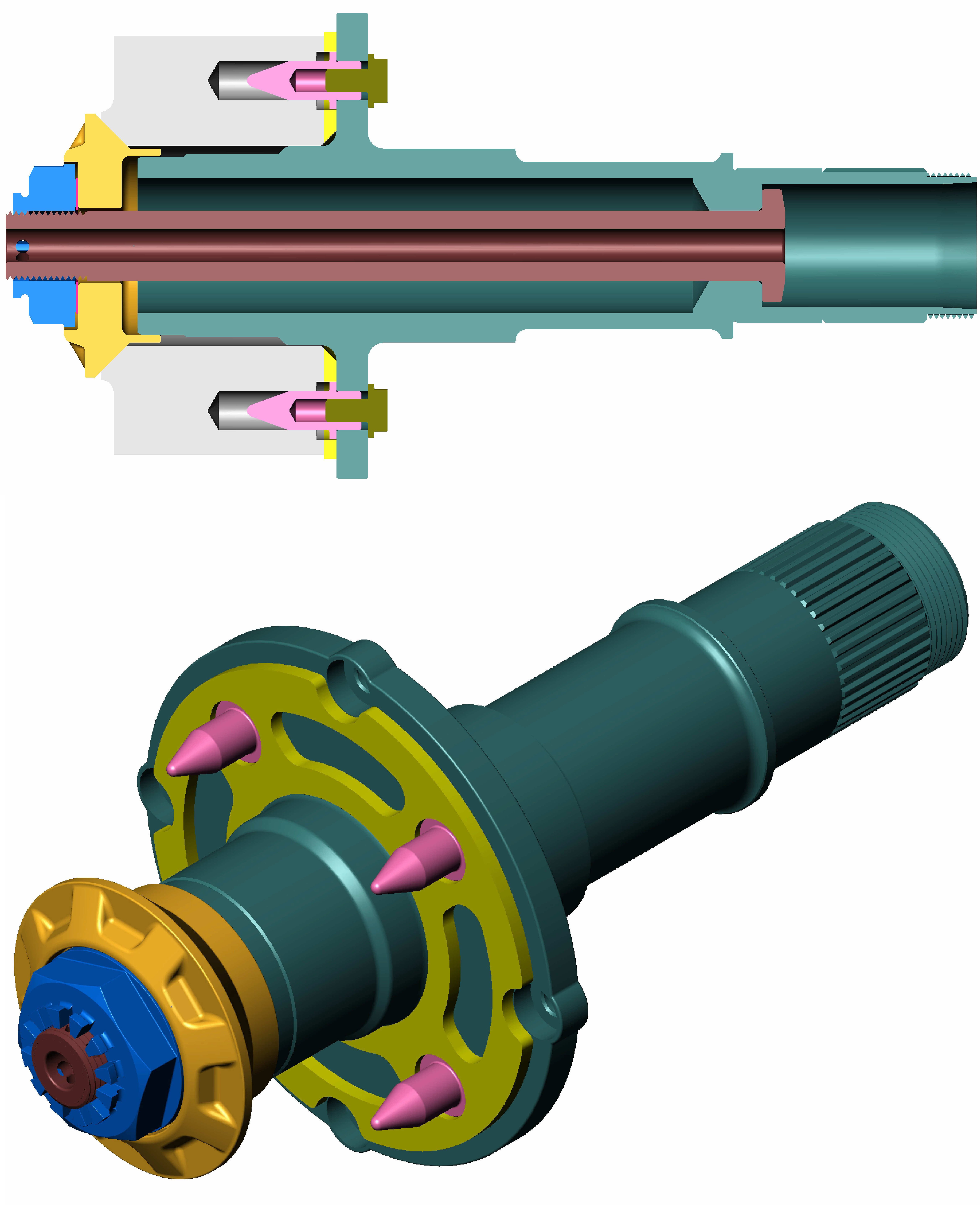
Below is a 3D Assembly Model of my setup with the bored out wheel, longer wheel pins, spacer between the modified wheel and axle, and a custom centerlock spacer. I like the fact I can easily put the original RC30 wheel on just by using stock parts. My custom pins still have clearance as Honda wheels are drilled very deep (see above in orange). If your nuts are this blue you need a girlfriend bad.
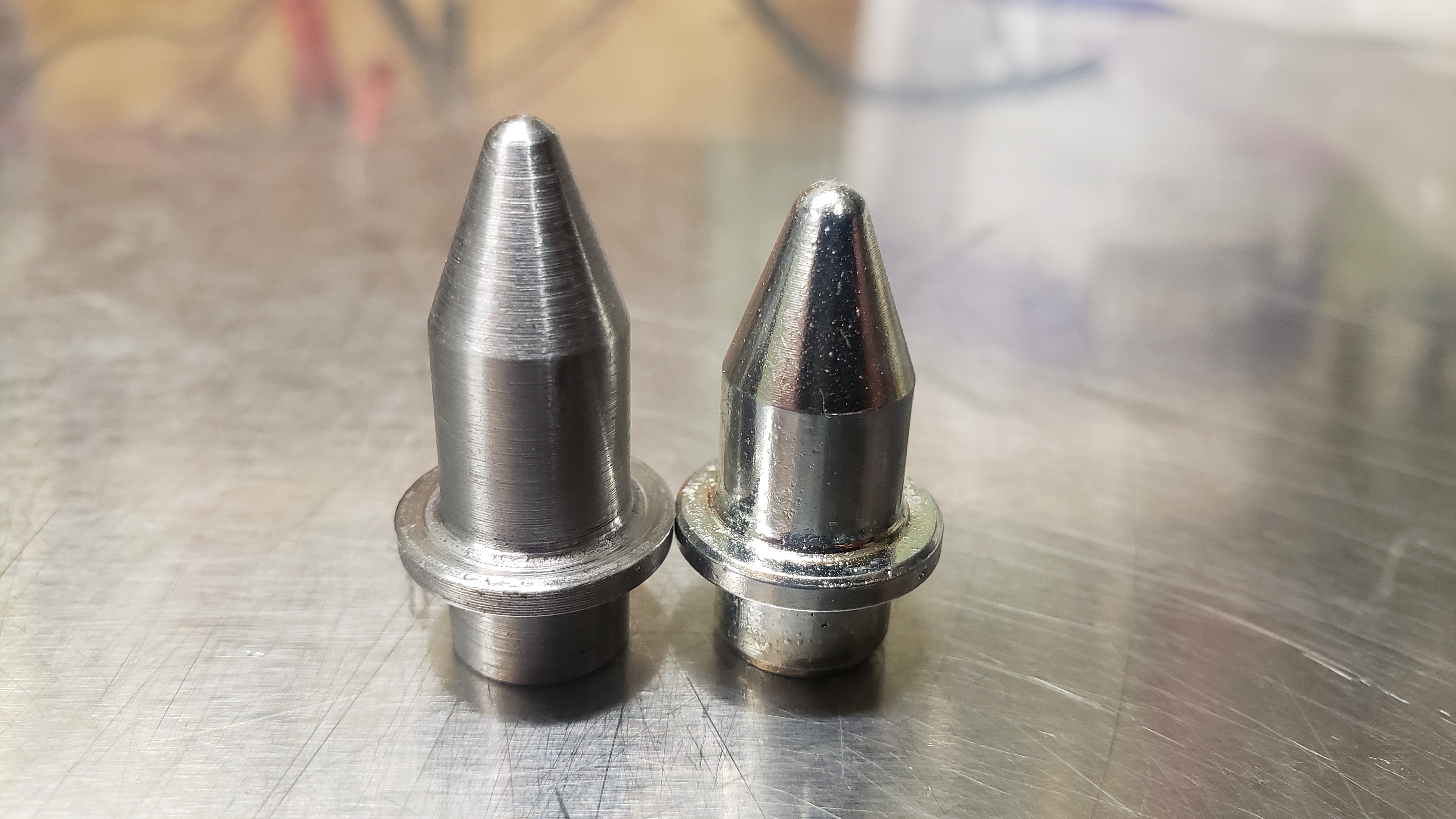
Custom wheel pin on the left alongside a Honda original. These are both threaded for 7mm x 1 mm/thread. The custom pins still need to be plated and chromate converted. The pins are made from RHS (really hard shit).
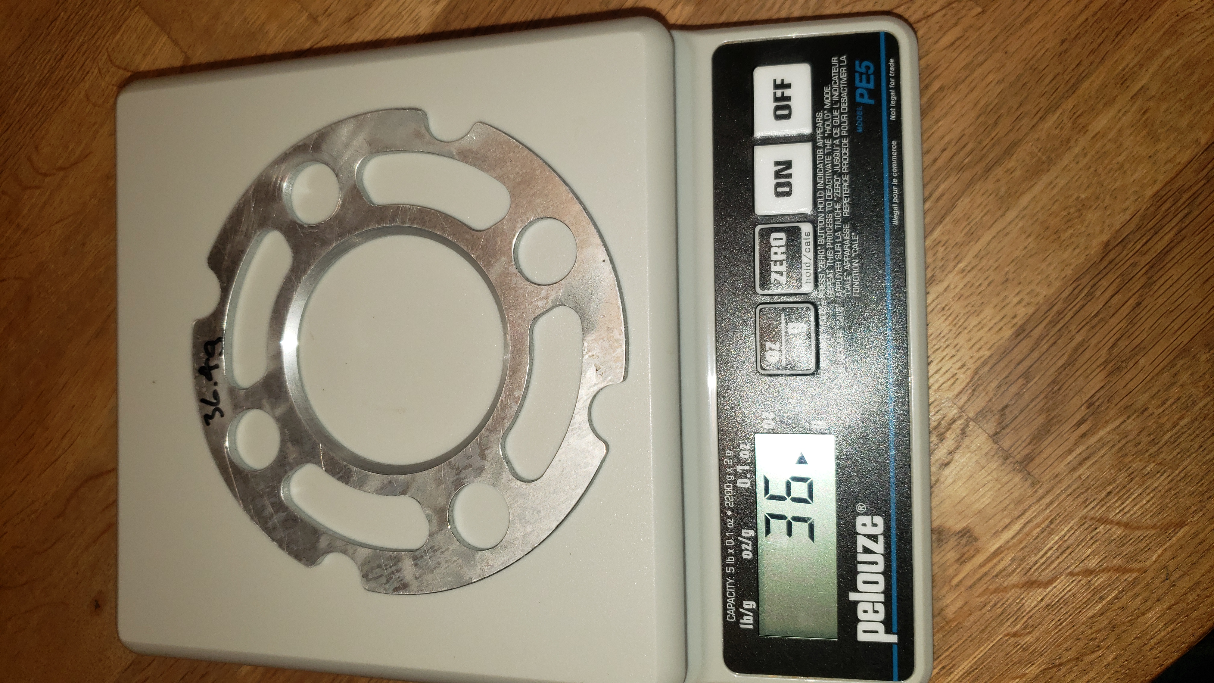
Below is the 3.18mm thick wheel spacer. Designed to go on the outside of the shoulder of the custom wheel pins. This was first cut out of aluminum sheet using an abrasive water jet. The 45 degree taper on the ID was subsequently cut on a lathe.
The side shown in the picture below goes towards the axle. The bevel is meant to clear the radius of the axle. You could just bore it bigger but the taper maximizes the wheel side pressure area (the soft aluminum side). The 36.4 grams written on it is a calculated weight from Solidworks.
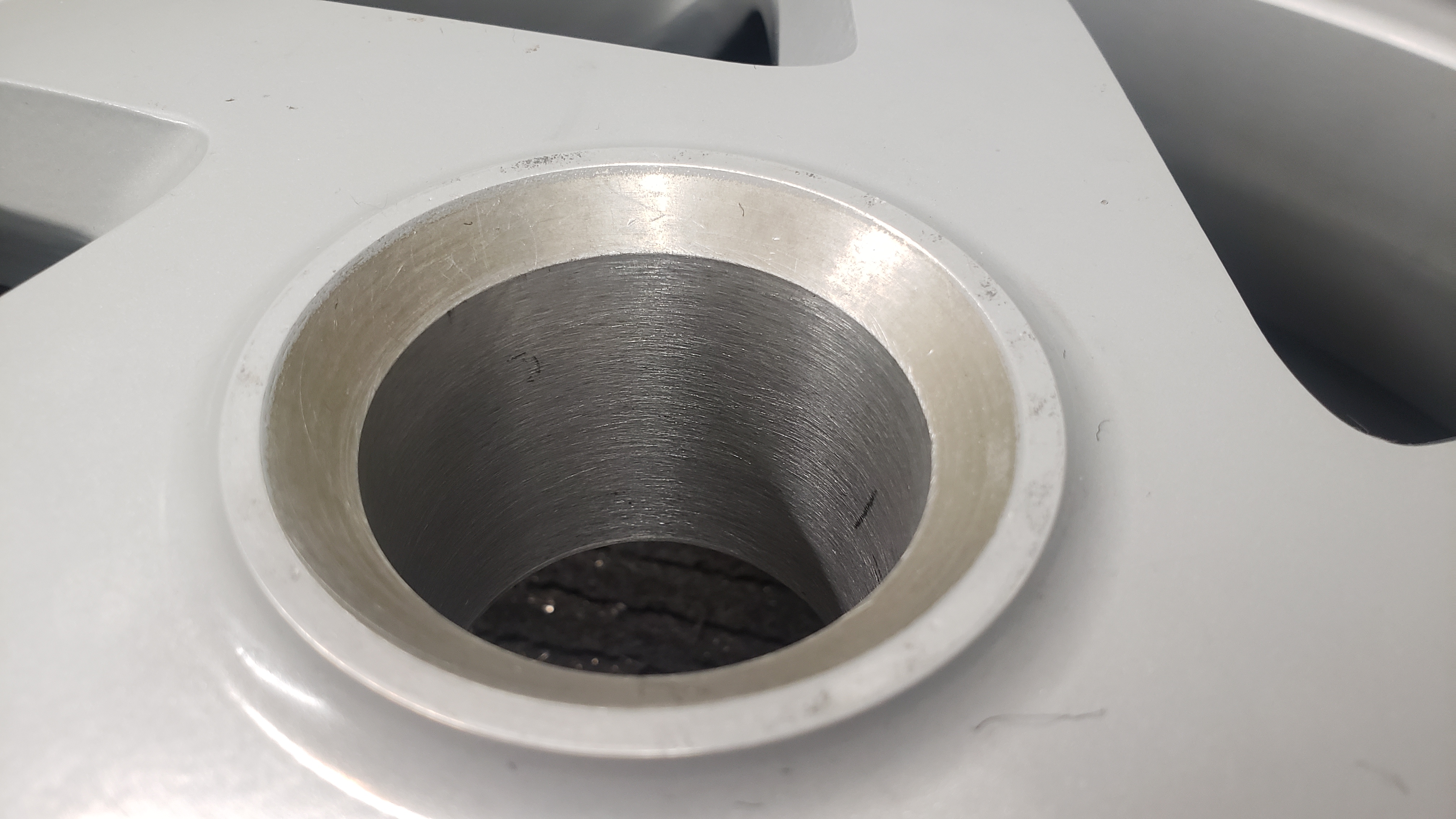
Below is the Ducati wheel after being bored out to match the RC30 wheel bore. This was done with a boring bar in a vertical mill (see picture further down of the wheel on the mill). The area of the taper is now 92% of the stock Honda wheel. I used Solidworks to get the approximate area of the tapered portions the centerlock spacer presses against:
- Stock Ducati Wheel - 2540mm2
- Bored Out Ducati Wheel - 1750mm2
- Stock Honda Wheel - 1900mm2
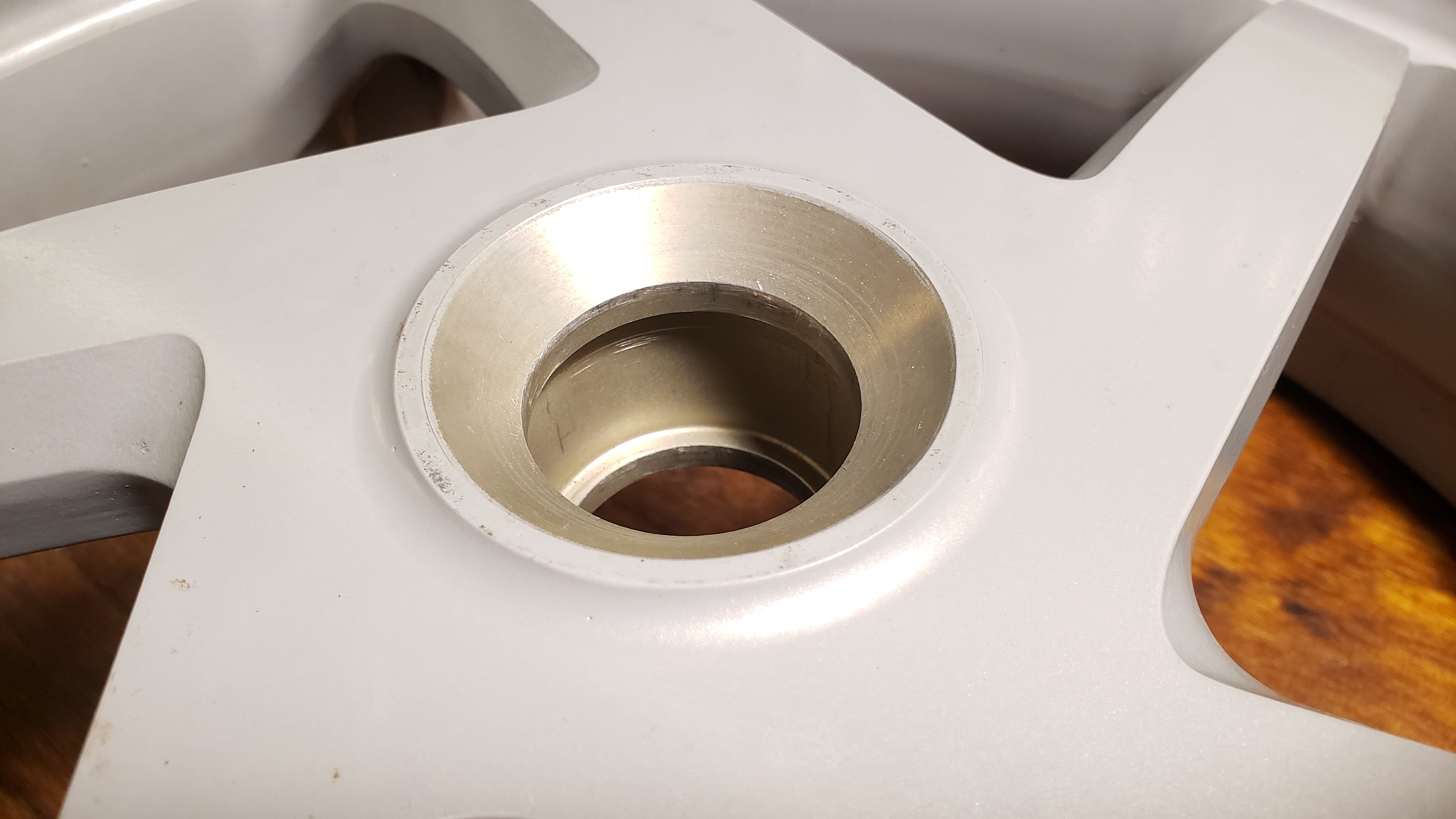
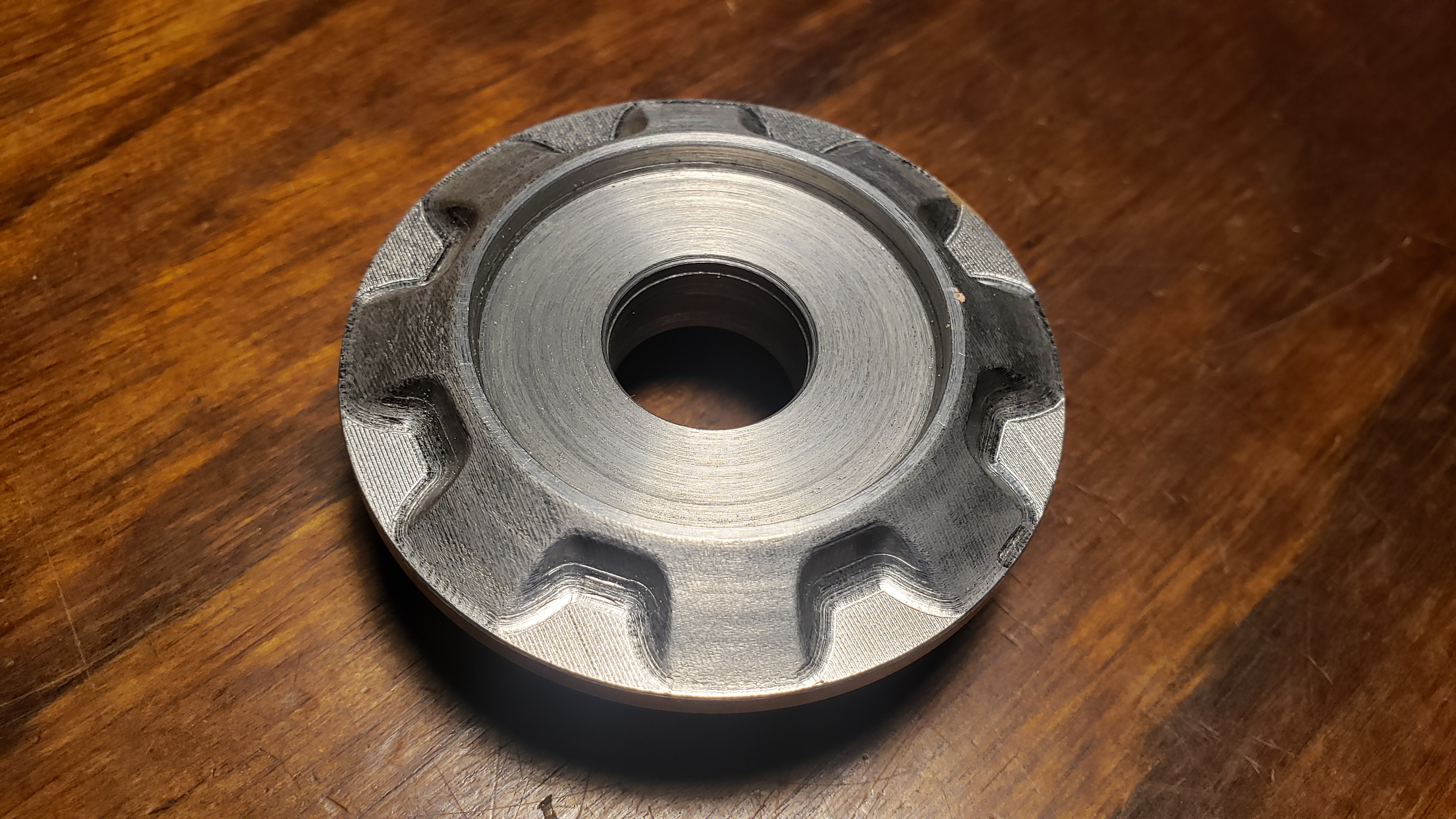
This is a picture prior to being bored out, just as Marchesini made it. The bore job doesn't remove as much material as it appears. It has more material remaining around the axle than the stock Honda wheel that is recessed.
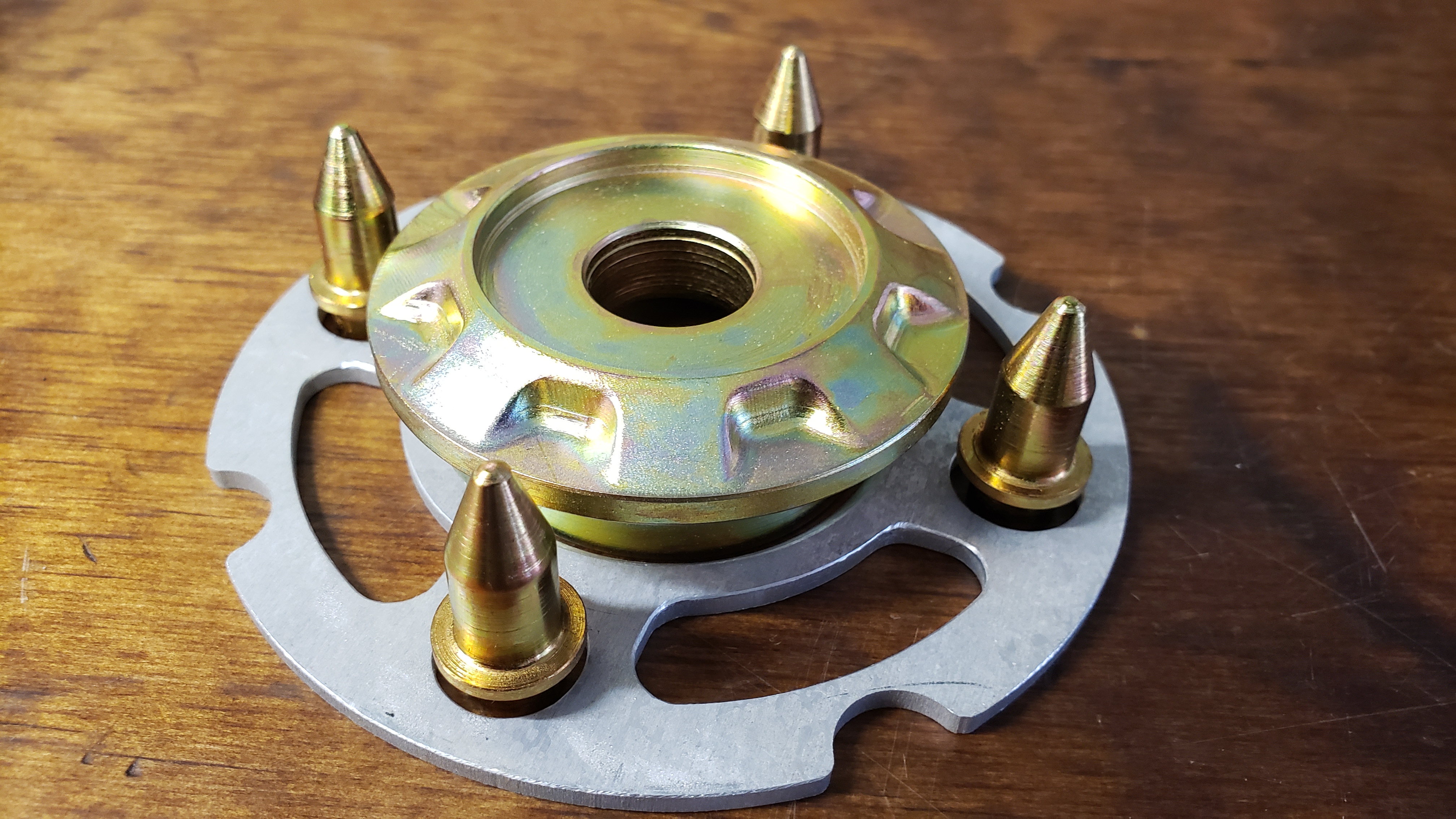
A look at the wheel spacer sitting in place. Those are still the original/short Honda wheel pins in the picture, they will get changed out. Changing them requires removing the axle. The cutouts for the brake disc bolts and the radial slots that match the Ducati wheel are not critical. It took just a moment on the water jet and I thought made it a bit snazzier looking, and a bit lighter. It avoids a pocket at the brake disk bolts too. This spacer snapped on it was cut so accurately. My neighbor is an incredible machinist, no wonder he taught every machinist around here at school. When I handed over the Solidworks 3D models and 2D drawings he knew exactly what to do, and what I was after. Nice to work with a motorcycle guy who is a machinist.
In the background you can see where a 170/60-18 Dunlop Roadsmart on a stock 18x5.5 wheel was hitting the swingarm a bit. Dunlops are always wider than published. Thankfully this came off with some WD40.
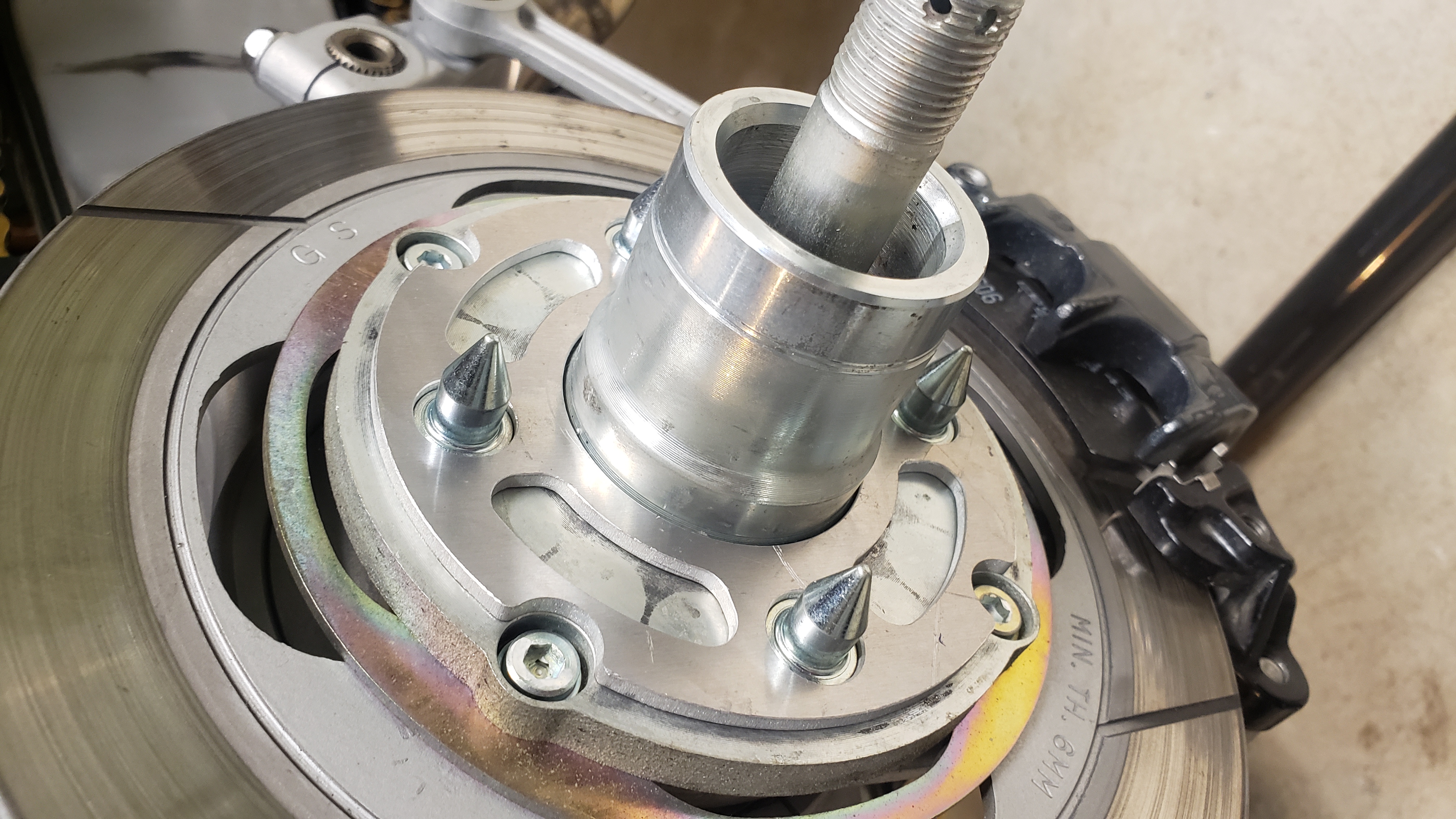
The bored out wheel sitting on the spacer. You can see how a stock centerlock spacer would fail to register on the large OD of the axle like the stock wheel and spacer. My custom centerlock spacer reaches in further.
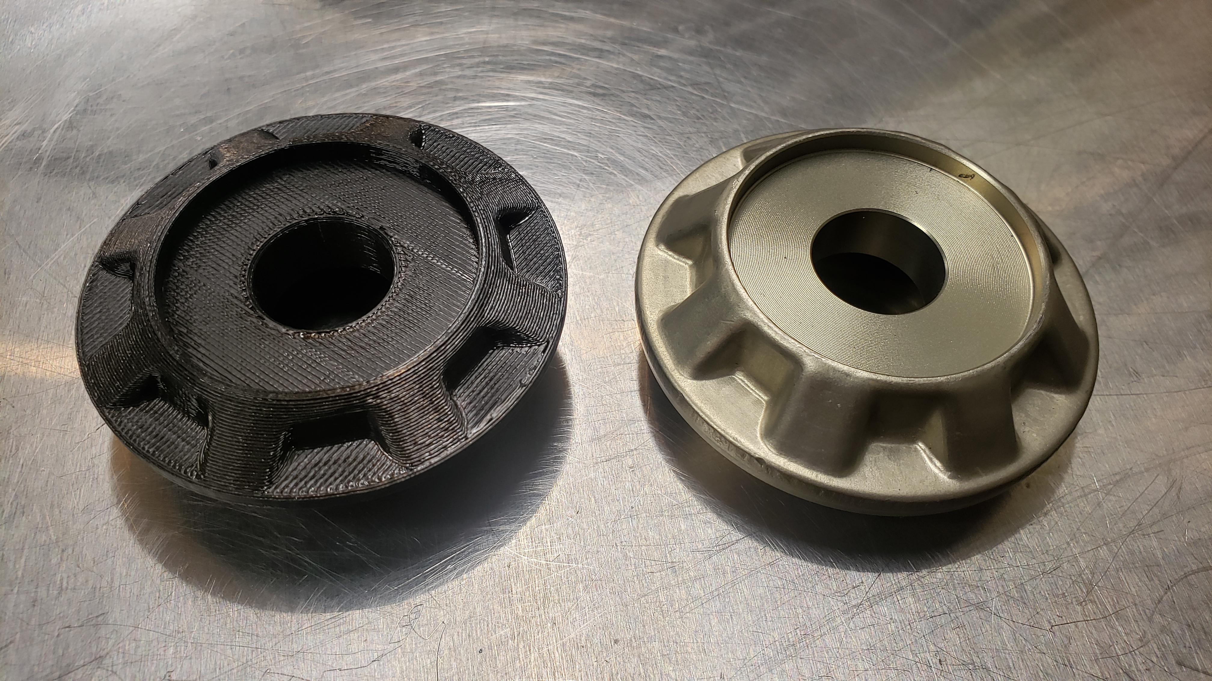
A prototype 3D print of my centerlock spacer on the left and a stock Honda centerlock spacer on the right.
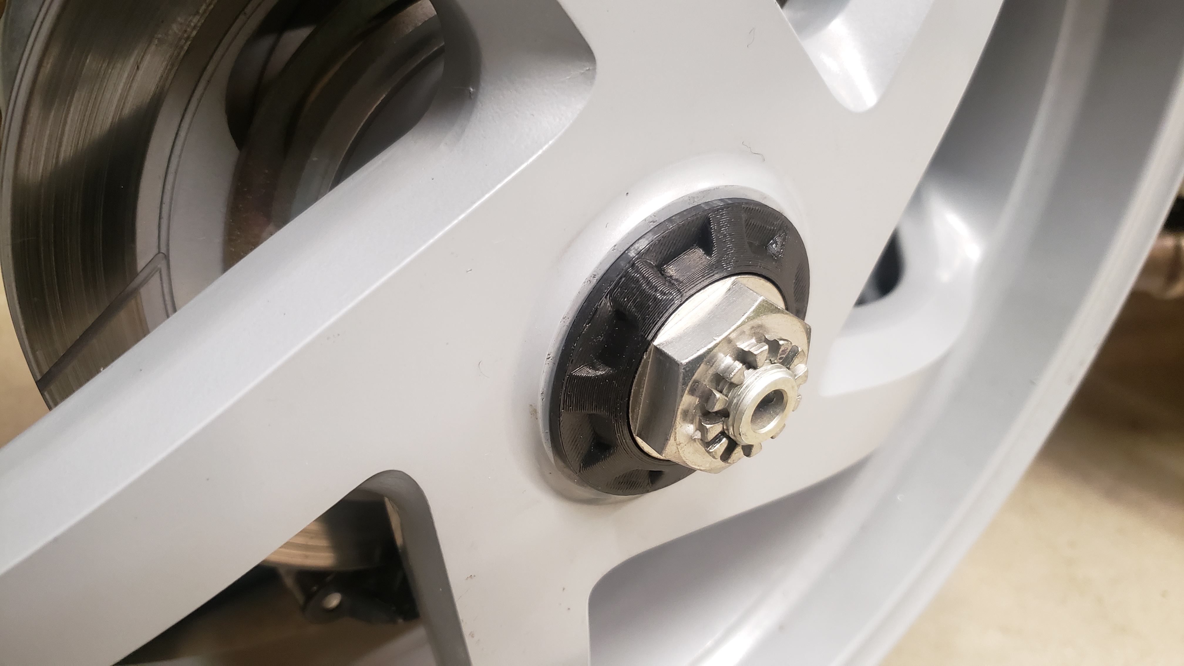
One last check on the nut depth and some other things with a 3D print of the centerlock spacer. Everything looks good so the 3D model is ready to be turned into metal. My neighbor made me a couple of these plastic ones just because he was as into it as I am.
My 3D Model turned into metal on the lathe. A CNC mill was used for the top surface to semi-replicate the original Honda forged ribs. These two pictures are metal in the raw before I cleaned it up a bit by glass bead blasting, zinc plating and chromating.
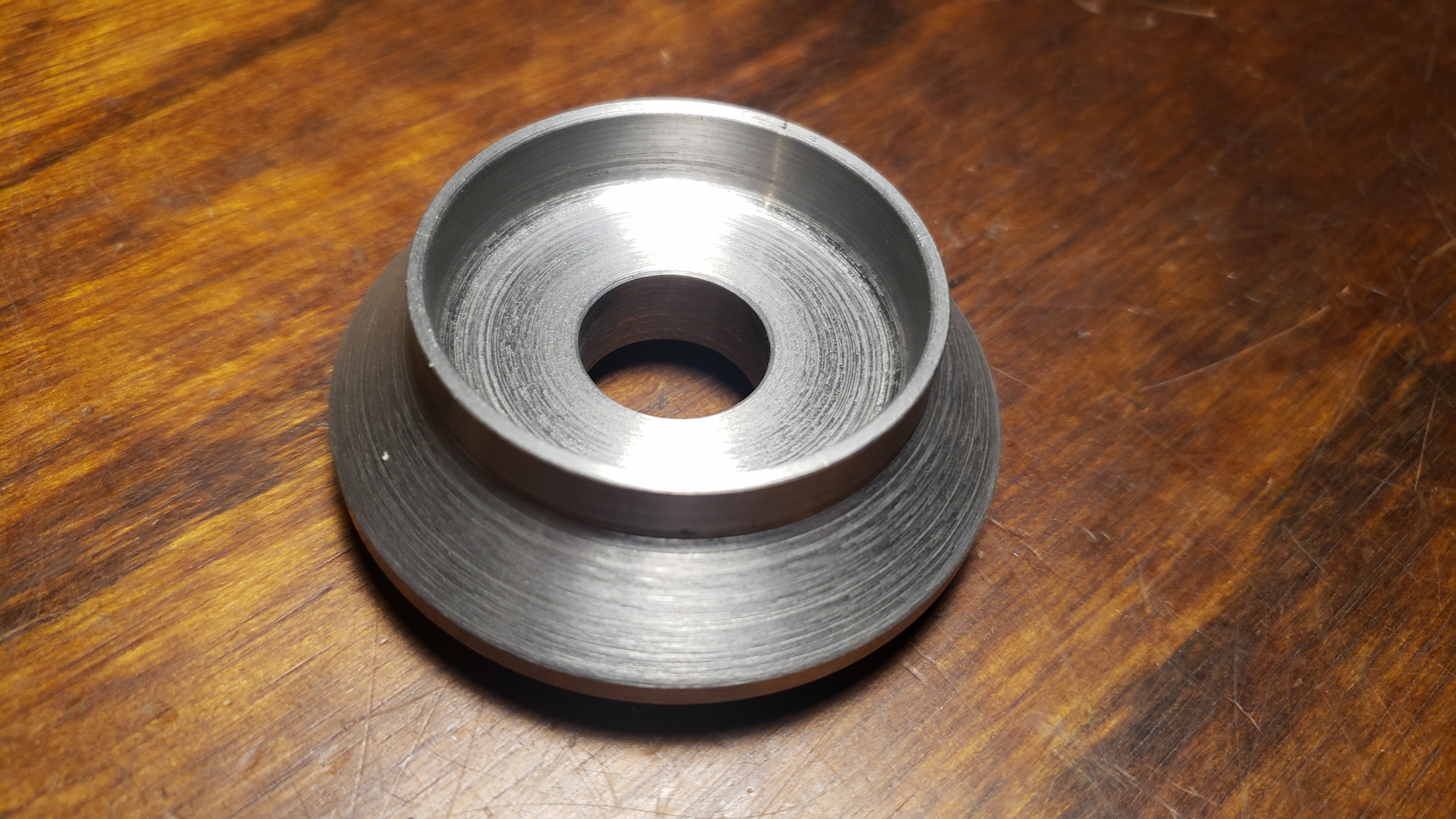
.
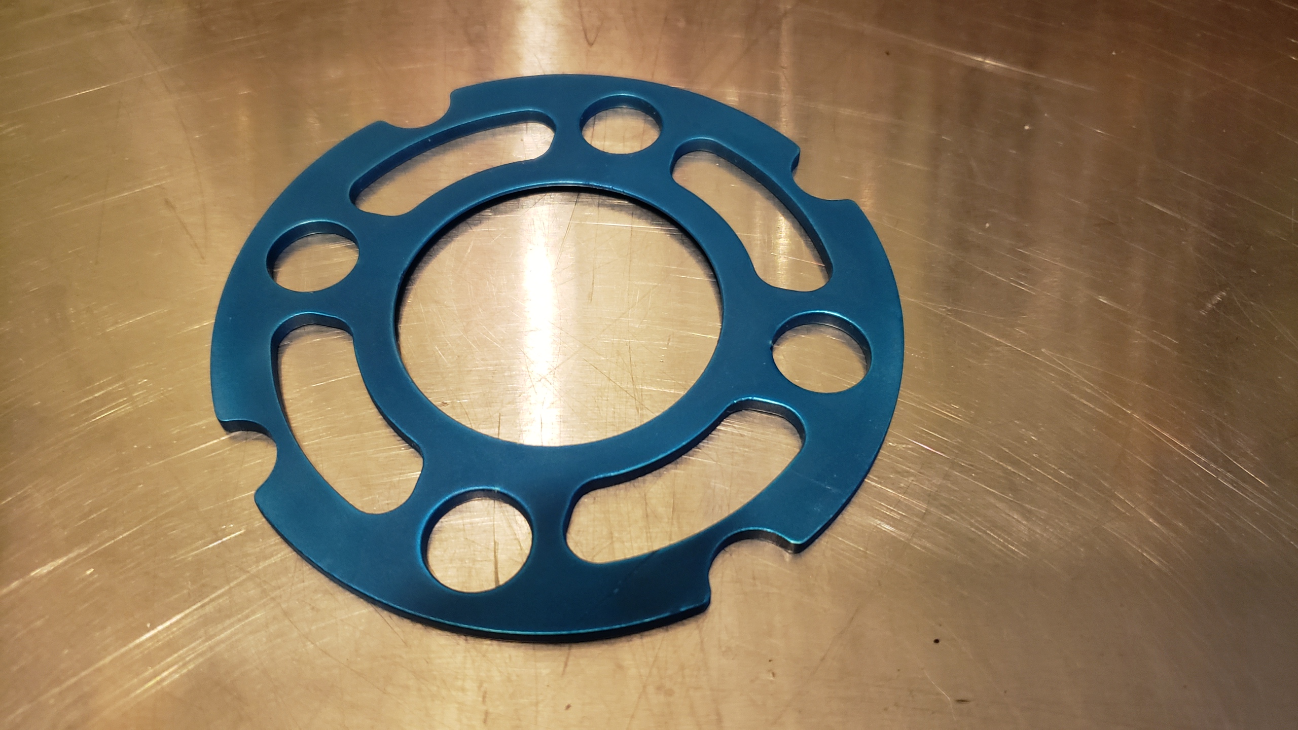
Here are the completed parts. The spacer was still in raw aluminum, it needs to be anodized. I will go with blue. You only see the outer edge of it anyway.
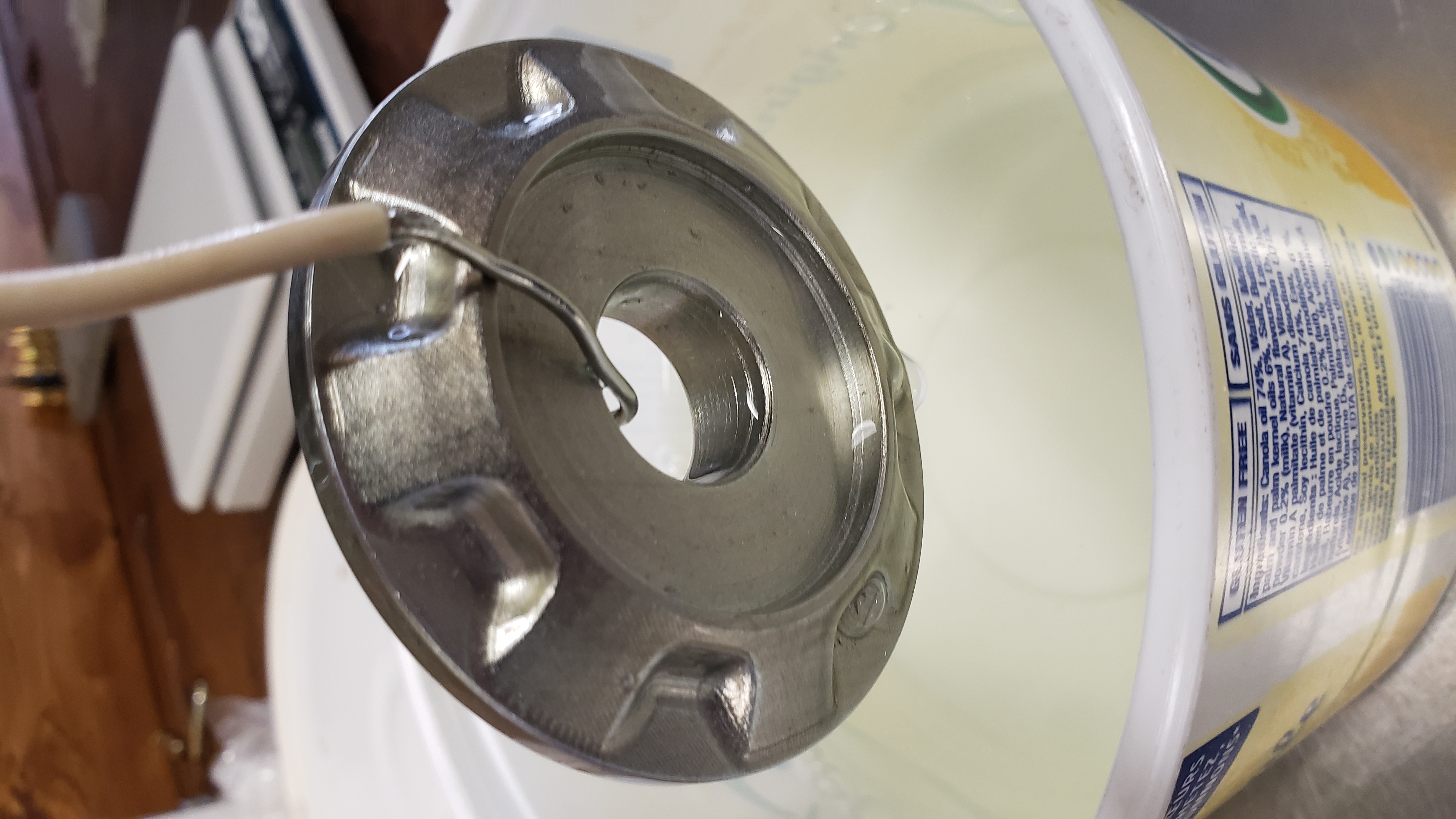
This is the wheel spacer after anodizing. I did this myself. All it took was some battery acid, anodizing dye, distilled water, titanium wire, a lead plate and my trusty old Hewlett Packard power supply. It worked pretty good considering I never did it before. It feels silky smooth now. If you ever do anodizing you will need a nice constant current power supply. Don't even think about using a battery charger. It isn't shiny because I glass beaded it. It's what gave it the silky feel.
This is a good image of my neighbor boring out the wheel to clear the RC30 axle. He wanted to test out his beautiful new Czech made boring tool, so we were both happy. His garage based shop is impressive! I am envious. 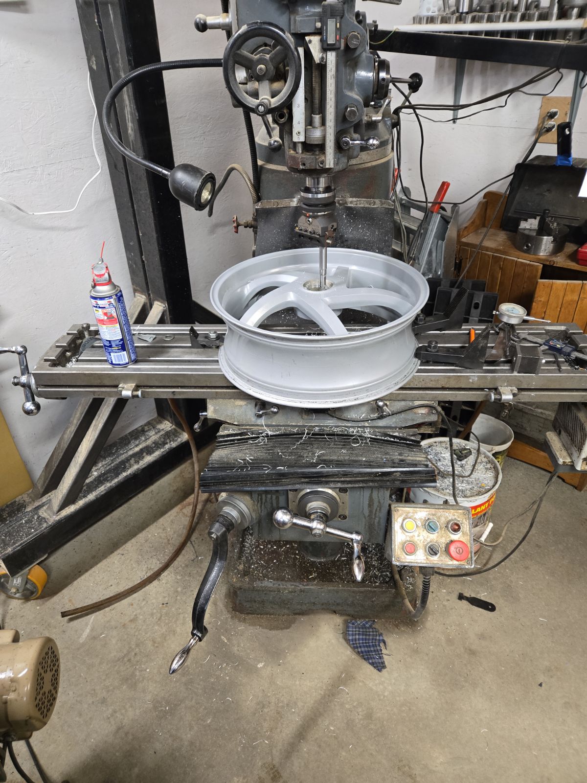
The custom made wheel spacer after zinc plating but prior to the chromate conversion coating to make it look more like an original Honda item.
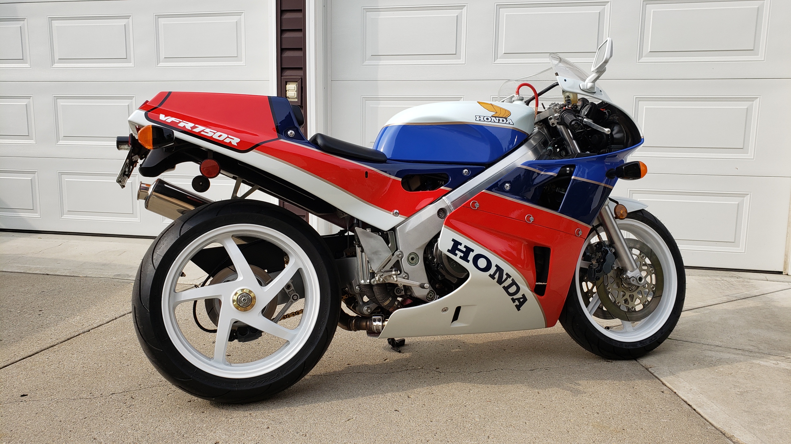
The final product with the wheel powdercoated and some fresh Michelin 2CT rubber. I had to raise the rear up 1/2" on the ride height adjuster to compensate for the smaller diameter 17" wheel. I really like the looks of the wheel and I can still put a stock rear on if I want.
Front - 120/70-17 on 3.5" wide wheel
Rear - 170/60-17 on 5.5" wide wheel
This rear is quite narrow, I like that it clears the chain and swingarm by about 1/4".
Here are some drawings I extracted from the 3D solid models for my neighbor to work off. I purposely removed some information, mostly materials, heat treatment and some dimensions. You get the idea though. These drawings are only meant to serve as inspiration not as drawings for your own wheel conversion. I may have put a wrong dimension in here and there just to see if you are paying attention.